The engine fuel system is forced, with fuel supplied by a diaphragm-type fuel pump
The engine is fueled by motor gasoline with an octane rating of at least 76 (GOST 2084-67).
Using lower-quality motor gasoline may cause abnormal engine operation (detonation, increased carbon deposits, increased fuel consumption, burnout of gaskets and cylinder heads, etc.).
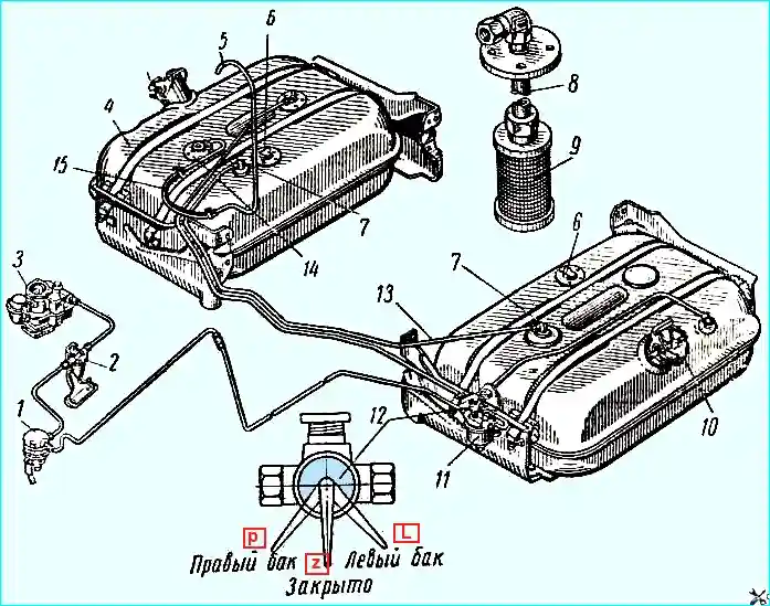
Fuel system diagram: 1 - fuel pump; 2 - fine fuel filter; 3 - carburetor; 4 - fuel tank (additional); 5 - air supply pipe; 6 - fuel level indicator sensors in tanks; 7 - elbows; 8 - intake pipe; 9 - mesh filter; 10 - plug; 11 - sediment filter; 12 - tap; 13 - connecting pipe of tanks; 14 - tank valve box: 15 - rubber hose; (P) - right tank; (L) - left tank; (Z) - closed
The main and additional fuel tanks, with a capacity of 170 liters each, are located on both sides of the frame under the cargo platform.
The filler necks of the tanks are closed with sealed hinged lids with quick-release clamps (Fig. 2).
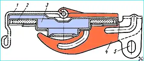
Tank plug: 1 - plug lining; 2 - rubber gasket; 3 - body; 4 - tank plug lever; 5 - hole for locking the plug on the neck
The right fuel tank is equipped with a valve box (Fig. 3) with automatically operating valves (inlet and outlet), connecting the cavity of the fuel tank to the atmosphere in the event of an increase or decrease in the internal pressure in the tank.
The left fuel tank is connected to the right fuel tank by an air tube.
When the vacuum in the tank is 0.016-0.034 kg/cm 2, the inlet valve 3 of the valve box opens and the tanks communicate with the ambient air.
When the pressure in the tanks increases by 0.11-0.18 kg/cm 2, the outlet valve 4 opens
This design of the valve box ensures equalization of pressure in the tanks and reduces fuel loss from evaporation.
The valve is connected to an air tube, which is brought out above the level of the specified ford and secured to the rear wall of the cabin.
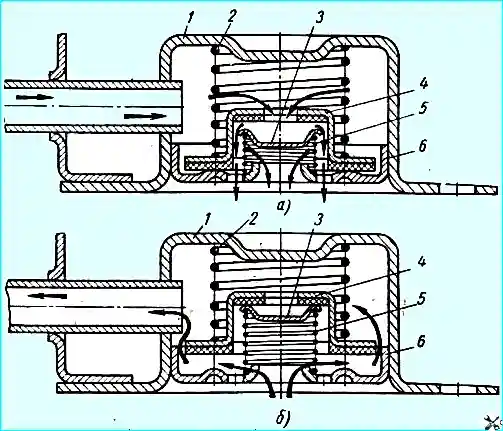
Fuel tank valve box: (a) - inlet valve in the open position when there is a vacuum in the tank; (b) - outlet valve in the open position when there is excess pressure in the tank; 1 - valve body; 2 - outlet valve spring; 3 - inlet valve; 4 - outlet valve; 5 - inlet valve spring; 6 - valve bottom
If a long parking is expected after filling the fuel tanks, it is recommended not to fill the right tank completely to avoid fuel leaking out through the valve when the outside temperature rises.
There is a hole 5 in the quick-release clamp lever of the plug (see Fig. 3), which coincides with the hole in the neck bracket when the plug is closed.
When driving off-road, to eliminate cases of spontaneous opening of the plugs as a result of snagging in the holes of the plugs and neck brackets, it is necessary to hang a lock or insert a bolt with a nut.
During operation, it is necessary to periodically check and tighten the fastening of the fuel tanks and brackets, drain the sediment through the drain plugs and flush the tanks, clean and flush the valves on the additional tank and blow out the tubes connecting the main and additional tanks.
If both tanks are full, fuel should be used first from the main (left) tank.
Fuel should be used from the additional (right) tank only if it is impossible to fill the main tank with fuel.
The tanks are switched using a valve installed on the bracket of the main tank's sediment filter.
The valve has three positions: the main tank is on, the additional tank (right) is on, and the valve is closed (see Fig. 1).
The fuel level in the tanks is monitored by a level indicator installed on the instrument panel.
The fuel level indicator can be connected to any tank, regardless of which tank the fuel is being used from.
The fuel level indicator switch is installed on the front shield of the cabin. The right position corresponds to connecting the right tank, the left position to the left tank.