Steering gear disassembly
Steering gear disassembly and assembly, as well as the pump, should only be performed if necessary by qualified mechanics in completely clean conditions
Before disassembly, the steering gear must be removed from the car, for which you should:
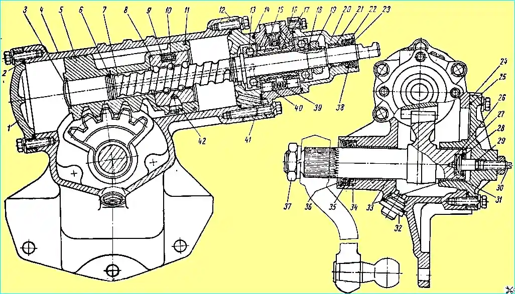
Steering gear: 1 - lower cover; 2, 14, 25, 29 and 41 - sealing rings; 3 - plug; 4 - steering gear housing; 5 - rack-and-pinion piston; 6 - split sealing ring; 7 - steering screw; 8 - ball nut; 9 - groove; 10 - ball; 11 - split piston rings; 12 - intermediate cover; 13 - thrust ball bearing; 15 - ball valve; 15 - spool valve; 17 - control valve housing; 18 - spring washer; 19 - adjusting nut; 20 - upper cover; 21 - needle bearing 22 and 35 - oil seal thrust rings; 23 - outer sealing cuff; 24 - side cover; 26 - thrust washer; 27 - adjusting washer; 28 - lock ring; 30 - adjusting screw; 31 - bipod shaft; 32 - drain plug with magnet; 33 - bipod shaft bushings; 34 and 38 - oil seals; 36 - rubber cuff; 37 - bipod shaft nut; 39 - reaction spring; 40 - reaction plunger; 42 - set screw
- - unscrew nut 37 (see Fig. 1) and remove the bipod using a puller: knocking the bipod together can cause breakage of parts;
- - unscrew the plug with magnet and drain the oil; for more complete draining, turn the steering wheel 2-3 times from one extreme position to the other;
- - disconnect the hoses, drain the remaining oil in the pump;
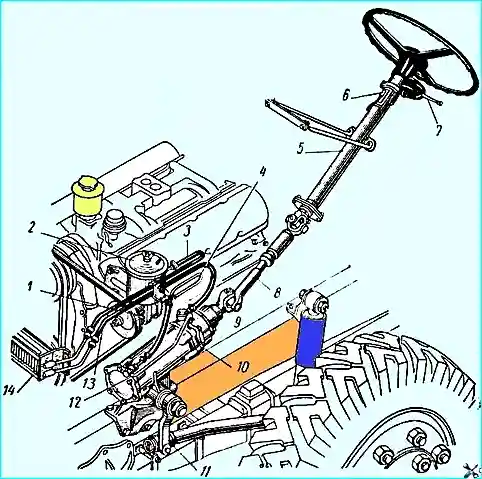
- - disconnect the propeller shaft by removing the cotter pin, unscrewing the wedge nut 9 (see Fig. 2) and knocking out the wedge;
- - unscrew the five bolts securing the steering gear housing to the frame;
- - thoroughly clean and rinse the outer surface of the steering gear;
- - drain the remaining oil by turning the steering gear upside down with the valve down and turning the screw 2-3 times from one extreme position to the other.
Disassembly and inspection of the steering gear must be performed in the following order:
- 1. Remove the bot cover together with the pitman arm shaft by unscrewing seven bolts.
- When removing the pitman arm shaft, clean its splined end and be careful not to damage the oil seal and sealing ring.
- 2. Remove the top cover by unscrewing four bolts; when removing the cover, be careful not to damage the oil seal and sealing ring.
- 3. Remove the control valve body together with the screw, piston rack and intermediate cover by unscrewing six bolts.
- 4. Remove the lower cover by unscrewing six bolts.
- 5. Check the tightening of the thrust ball bearing nut.
The torque required to turn the control valve body relative to the screw should be 6-8.5 kgf.cm.
- 6. If the conditions specified in paragraph 5 are not met, adjust the tightening of the nut or, if the ball bearings are damaged, replace them.
To adjust the tightening of the nut, first press the flange of the nut pressed into the screw groove, protecting the screw thread from damage, unscrew the nut, clean the groove in the screw and the thread in the nut.
The conical disc spring must be installed between the ball bearing and the nut with the concave side facing the ball bearing.
After adjusting the tightening of the nut, its flange must be pressed into the screw groove without breaking; the extrusion must be rounded, without sharp corners.
- 7. Check the axial movement of the adjusting screw 30 (see Fig. 1) in the pitman arm shaft. If the movement exceeds 0.15 mm, replace the adjusting washer 27, bringing the movement to 0.02-0.08 mm.
- 8. Check for axial movement of the ball nut relative to the piston-rack. If necessary, tighten or replace the two set screws and punch them.
- 9. Check the fit of the ball nut and the middle part of the screw. The nut on the screw must rotate without jamming, and the axial displacement relative to the screw must not exceed 0.3 mm.
- 10. If the conditions specified in paragraph 9 are not met, replace the balls or the entire set (ball nut and screw with balls), for which:
- a) unscrew the two set screws 42 securing the ball nut, using a special key with a sufficiently large shoulder;
- b) remove the ball nut with the screw from the piston-rack, holding the grooves and balls from falling out;
- c) remove the grooves and, turning the screw relative to the nut in both directions, remove the balls;
- d) remove the intermediate cover.
- 11. If the screw raceways of the nut or screw are damaged, replace them.
- 12. In case of replacing a set - a nut and a screw with balls - their completeness must not be violated during assembly, since they are selected individually at the factory.
- 13. In case of replacing only the balls with a larger size, take balls of the same size group (with a difference in size of no more than 0.002 mm).
Installing balls with a difference in size of more than 0.002 mm can lead to breakage of the balls and jamming of the steering.
See below for the assembly procedure of the ball nut.
- 14. After replacing the balls, the nut should rotate in the middle part of the screw under a torque of 3-8 kg/cm, and the fit at the edges of the screw should be loose
Assembling the steering gear
- 1. Before assembly, all parts must be thoroughly washed and dried. Do not wipe parts with the ends of rags that leave threads, lint, etc. on the parts.
- 2. All rubber sealing parts must be inspected and, if necessary, replaced.
- 3. The tightening torque must be 2.1-2.8 kgm for MB bolts and 3.5-4.2 kg/m for M10 bolts.
- 4. The piston rings must move freely in the grooves.
- 5. To assemble the ball nut, it is necessary to:
- a) put the intermediate cover and nut on the screw, install the nut on the lower end of the screw that does not have a flange, aligning the holes in the nut, into which the grooves 9 (see Fig. 1) enter, with the screw helical groove;
- b) insert 23 balls through the hole in the nut facing the screw flange, turning the screw counterclockwise; insert eight balls into the grooves folded together and prevent them from falling out by smearing the outlets with consistent grease UP (technical petroleum jelly), GOST 782-59;
- c) insert the grooves with balls into the nut, turning the screw if necessary; tie the nut to prevent the grooves from falling out of the nut;
- d) check the torque of the nut on the middle part of the screw and replace the balls if necessary;
- d) screw on the set screws 42, tightening them with a torque of 5-6 kgm, and punch each screw in two places against the grooves in the piston-rack.
If the groove in the piston-rack coincides with the screw spline, the latter must be replaced.
Protrusion of screws or presses above the cylindrical surface of the piston-rack is unacceptable, as it causes scoring of the power steering cylinder.
The piston ring locks must be located at an angle of 900 and installed symmetrically in the upper part of the cylinder.
- 6. The completeness of the spool valve of the reaction plungers and the control valve body must not be violated during disassembly, since they are individually selected at the factory.
In case of overhaul of the control valve, it is necessary to ensure that the groove on the end of the spool valve is facing upwards from the middle flange of the screw, and the chamfers on the reaction plungers 40 are facing outwards.
The spool valve and reaction plungers must move smoothly in the control valve body, without jamming.
- 7. In case of replacing the needle bearing 21 of the upper cover, it must be pressed in so that after pressing in the marking on its end is visible.
- After pressing in, the bearing needles must move freely in the bearing race.
- 8. The pitman shaft seal must be protected from damage by the shaft splines during assembly.
The final pressing of the pitman shaft seal 34 is carried out together with the thrust ring 35, the cuff 36, the washer and the locking ring until the locking ring snaps into place in the groove.
The locking ring must fit into the crankcase groove along the entire perimeter.
- 9. In the assembled steering gear, after turning the steering screw 7 until the piston stops in both directions, apply additional torque to the screw, achieving its movement in the axial direction.
- Springs 39 must ensure its return to its original position.
- 10. Adjust the adjusting screw 30 so that when passing through the middle position, the torque of the screw 7 is greater than the same torque before adjustment by 10-15 kgf/cm.
In this case, the torque when passing through the middle position should not exceed 50 kgf/cm.
After adjustment, lock the screw 30 with a lock nut to a torque of 4-4.5 kgf/cm and then check the torque of the screw p again left-hand control.
- 11. The rotation of the bipod shaft from one extreme position to the other must occur with a torque of no more than 8 kgm applied to it.