The handbrake is adjusted to reduce the gaps between the shoes and the drum, which have increased due to wear of the linings.
The presence of large gaps is detected by an increase in the travel of the drive lever.
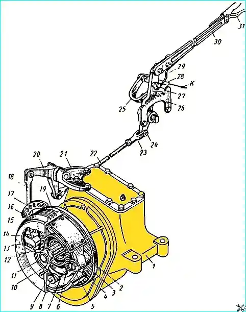
The handbrake is adjusted with rod 22 and adjusting lever 17.
Adjustment is made on a cold brake in the following order:
- 1. Disconnect the threaded fork 23 of the rod 22 of the drive from the lever 30.
- 2. Move the lever 30 to the front extreme position until it stops.
- 3. By changing the length of the rod 22 with the threaded fork 23, achieve such a position that after connecting the rod to the lever 30, complete braking occurs when the locking latch moves by four to six teeth of the sector 26, and when returning the lever 30 to the forward position, the drum rotates freely without touching the brake shoes.
If the rod shortened to the limit does not ensure braking when the locking latch moves by six teeth of the sector, then it is necessary to move the pin 16, to which the lower end of the rod 18 is attached, to the next hole of the adjusting lever 17 of the brake, securely tighten the nut and cotter pin.
After this, make the adjustment in the same way as indicated in paragraphs. 2 and 3.
Maintenance of the handbrake and drive. Maintenance of the handbrake and drive consists of periodic inspection, cleaning from dirt and checking the fasteners.
If less than 0.5 mm remains from the surface of the brake linings to the rivet heads, then the linings must be replaced.
It is necessary to protect the pad linings from oil, as this may change their friction properties.
The rubbing surfaces of the hinge joints of the brake and drive must be periodically lubricated using an oil dropper.
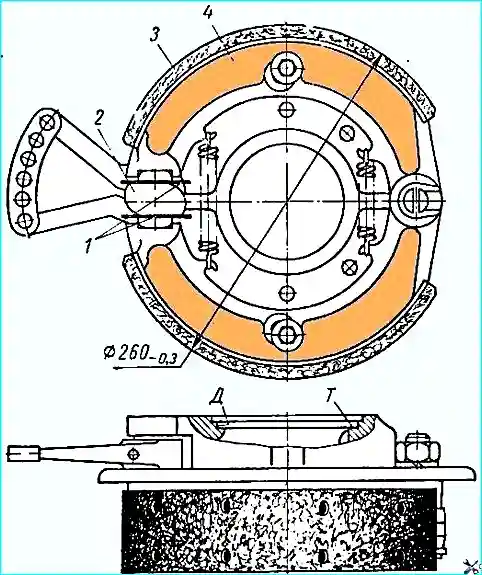
Fig. 2 shows the size according to which the working surface of the brake shoes should be processed after installing new friction linings.
The diameter of the shoes (260-0.3 mm) is given in relation to new drums.
After boring the drum during repair, the diameter of the shoes should be equal to the diameter of the drum.
When processing the linings, plates 1 with a thickness of 1± 0.02 mm must be clamped between the expanding cam and the shoes, as shown in Fig. 2.
When installing the brake on the surface (D) and supporting it on the end (T), the runout of the working surface of the brake shoes should not exceed 0.2 mm.
After processing the linings, the plates must be removed.
When disassembling the handbrake, incorrect removal of the release springs 6 and 12 (Fig. 1) of the shoes can lead to breakage of the hooks on them.
The most convenient way to remove the springs is with special pliers, which can be made.
If pliers are not available, it is recommended to remove the shoes in the following order.
Unscrew bolt 8 and remove limit washer 9.
Bend pin 5 and remove it together with the washer.
Then simultaneously remove the shoes from the axle of the expanding cam, after which the springs can be easily will be released.
The pads should be installed in the reverse order, i.e. hook the springs onto the hooks on both pads, spread the pads apart and place them on the axle and knuckle, and then secure them.
")

")
")
")
")
")
")
")