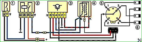
The ignition system is contactless. Consists of a distribution sensor, switch, ignition coil, spark plugs, ignition switch and high and low voltage wires
Ignition distributor sensor 3810.3706 - four-spark, with a contactless control pulse sensor and built-in vacuum and centrifugal ignition timing regulators.
The initial ignition timing angle at a crankshaft speed of 750–800 min –1 should be 1±1° BTDC.
The distribution sensor performs two main functions: firstly, it sets the moment of spark formation depending on its initial setting, the crankshaft speed and the engine load, and secondly, it distributes high voltage pulses (“spark”) among the cylinders in accordance with the order of their operation - a rotor (runner) is used for this.
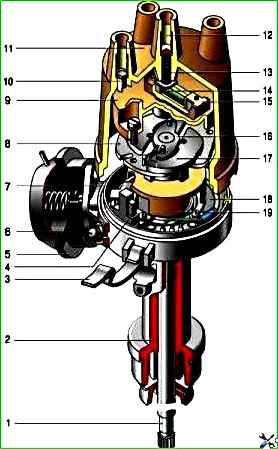
Ignition distributor sensor 3810.3706: 1 - roller; 2 - ignition sensor-distributor housing; 3 - latch; 4 - contactless sensor; 5 - vacuum regulator housing; 6 - diaphragm; 7 - vacuum regulator rod; 8 - support plate of the centrifugal regulator; 9 - ignition distributor rotor; 10 - side electrode; 11 - cover; 12 - central electrode: 13 - ember of the central electrode; 14 - resistor; 15 - external contact of the rotor; 16 - driving plate of the centrifugal regulator; 17 - centrifugal regulator weight; 18 - contactless sensor support plate; 19 - screen
In order to avoid mistakes during assembly, the slider is installed on the support plate of the centrifugal regulator in only one position.
The slider has a 1 kOhm noise suppression resistor.
The operation of a non-contact sensor is based on the Hall effect.
When the ignition is turned on, power supply is supplied to the sensor.
When the sensor-distributor roller rotates, a steel screen with rectangular cutouts passes through the sensor gap.
As long as there is a screen plate in the gap, the voltage is removed from the control terminal of the sensor; as soon as there is a cutout in the gap, the voltage at the control terminal drops sharply.
Thus, the contactless sensor produces four rectangular pulses (according to the number of cutouts in the screen) for each revolution of the distributor shaft, which corresponds to the ignition moment in each of the engine cylinders.
You can check the functionality of the contactless sensor by assembling the circuit shown in the figure.
Slowly rotating the ignition distributor shaft, monitor the voltmeter readings.
The voltage should change sharply from minimum (no more than 0.4 V) to maximum (no more than 3 V less than the supply voltage).
A faulty sensor cannot be repaired (except for a break in the wires between the sensor itself and the block on the sensor-distributor housing).
If a steel screen with slots touches the sensor (determined by a slight jamming or scratching sound when the roller rotates, as well as visually, after partially disassembling the distributor sensor), check the axial play of the roller and the fit of the screen.
If necessary, replace the distributor sensor.
The centrifugal regulator increases the ignition timing with increasing engine speed, coming into operation at 900–1400 min –1 .
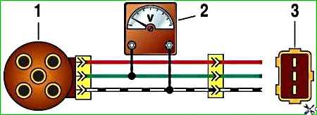
Scheme for checking a contactless sensor on a car: 1 - ignition distributor sensor; 2 - a voltmeter with a scale limit of at least 15 V and an internal resistance of at least 100 kOhm; 3 - view of the plug connector of the ignition distributor sensor
When the sensor-distributor roller rotates, the regulator weights diverge under the action of centrifugal forces, overcoming the resistance of the springs, and shift the support plate of the centrifugal regulator clockwise relative to the roller.
For optimal operation of the regulator, the springs have different stiffnesses.
The stiffer (thicker) spring comes into action later, approximately halfway through the full stroke of the plate - therefore, it is put on the stand with a gap, while the softer (thin) spring is always tense.
Ogre base plate maximum movement There is no cutout in it and is about 12° along the distributor, which corresponds to an ignition timing angle of about 24° along the crankshaft.
When inspecting the centrifugal regulator, make sure that the weights move freely on the axles, their damper plastic rings are not lost, the thin spring is tensioned, and the support plate returns under the action of the springs to its original position.
If necessary, lubricate the distributor shaft with a few drops of engine oil.
The vacuum regulator increases the ignition timing depending on the engine load.
It consists of a vacuum chamber with a steel spring-loaded membrane, which is connected by a rod to the base plate of the proximity sensor.
Under the influence of vacuum, the membrane bends, overcoming the resistance of the spring, and turns the support plate counterclockwise.
Maximum movement is limited by the cutout on the rod and is approximately 9° at the distributor (18° at the crankshaft).
The vacuum for operation of the vacuum regulator is taken from the hole in the mixing chamber of the carburetor opposite the throttle valve of the first chamber.
When the damper is partially opened (partial load), the vacuum behind it is large, and the regulator shifts the moment of spark formation as much as possible towards the advance.
When the damper is fully opened (full load), the vacuum behind it drops, and the regulator returns the contactless sensor support plate to its original position.
You can roughly assess the serviceability of the vacuum regulator directly on the car.
With the engine running, disconnect the vacuum hose leading to the regulator from the carburetor fitting.
If you now create a vacuum in the hose (you can use your mouth), the engine speed should increase, and when the vacuum is removed, it should decrease again.
The vacuum should remain for at least a few seconds if the hose is pinched.
You can visually verify the functionality of the vacuum regulator by partially disassembling the distributor sensor (see Repairing the ignition distributor sensor of a VAZ-2121 car) and applying a vacuum to the inlet fitting of the regulator.
In this case, the screen of the sensor-distributor should rotate at an angle of 9±1°, and when the vacuum is removed, return back without jamming.
Precise checking and adjustment of the vacuum and centrifugal ignition timing regulators is carried out on special stands.
If the vacuum regulator fails, it should be replaced; if the centrifugal regulator fails, the sensor-distributor should be replaced.
The switch - type 3620.3734, or HIM-52, or VAT10.2, or 76.3734, or RT1903, or PZE4022 - opens the power circuit of the primary winding of the ignition coil, converting the control pulses of the sensor into current pulses in the ignition coil.
The switch is checked with an oscilloscope using a special method and is not repairable; If a malfunction is suspected, it is recommended to replace it.
Do not disconnect the switch connector while the ignition is on - this may damage it (as well as other components of the ignition system).
Ignition coil - type 27.3705 or 27.3705-01, or 8352.12, or ATE1721 - oil-filled, with an open magnetic circuit.
Data for testing: resistance of the primary winding at 25°C – (0.45±0.05) Ohm, secondary winding – (5.0±0.5) kOhm. Insulation resistance to ground – at least 50 MOhm.
Replacing the coil and commutator is described in the article - “Replacing the coil and commutator”
Spark plugs - type A17DVR or A17DVRM, or A17DVRM1, or their imported analogues (with noise suppression resistors with a resistance of 4–10 kOhm). The gap between the electrodes is 0.7–0.8 mm.
High-voltage wires - with distributed resistance (2550±270) Ohm/m.
Do not touch high-voltage wires while the engine is running - this may result in electrical injury.
It is also forbidden to start the engine or allow it to operate with an open high-voltage circuit (removed wires or the distributor sensor cover) - this can lead to burnout of the insulation and failure of the electronic components of the ignition system.
As an exception, a short-term check of the ignition system “for spark” is allowed, in this case the contact of the high-voltage wire being tested must be securely fixed at a distance of 8–10 mm from the “ground” of the car.
Do not hold the wire with your hands or tools (even with insulated handles).
Ignition switch - type 2101-3704000-11, with anti-theft locking device.
When the key is turned to the “ignition” position, voltage is supplied to the control input of the additional relay, which, in turn, supplies voltage to the ignition coil and switch.