Front suspension – independent, on forked transverse steel levers, with helical cylindrical springs, double-acting telescopic hydraulic shock absorbers and anti-roll bar
The upper and lower arms have a similar design: at the ends of the "fork" there are cylindrical lugs for rubber-metal hinges (silent blocks), and on the opposite side there is a platform with three holes for attaching a ball joint.
On the front branch of the upper arm there is a lug against which the rebound buffer rests at maximum suspension travel, and on the lower arm there are four holes for attaching the lower support cup of the spring.
The ball joints of the upper and lower arms are interchangeable and unified with the upper ball joints of the VAZ-2101-2107 suspension.
The support is attached to the lever together with the boot and pressure plate with three bolts with spring washers and nuts.
The threaded ends of the pins of both the upper and lower supports are directed downwards and enter the conical holes of the steering knuckle.
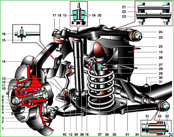
Front suspension components: 1 - brake disc; 2 - wheel hub; 3 - stud; 4 - lower ball joint; 5 - cap; 6 - outer joint housing of the drive; 7 - adjusting nut; 8 - conical bushing; 9 - hub bearings; 10 - oil seals; 11 - mud deflector ring; 12 - rubber cushion of the stabilizer bar; 13 - stabilizer bar mounting collar; 14 - steering knuckle; 15 - body; 16 - strut; 17 - ball pin protective cover; 18 - upper ball joint; 19 - shock absorber rod mounting cushions; 20 - upper arm; 21 - cross member; 22 - adjusting washers; 23 - upper arm axis; 24 - rubber-to-metal hinge (silent block) of the upper arm; 25 - rebound buffer; 26 - rebound buffer bracket; 27 - upper spring support cup; 28 - upper spring insulating gasket; 29 - spring; 30 - strut to cross member mounting bolt; 31 - Lower arm washers; 32 - Lower arm axle; 33 - Lower arm rubber-metal hinge; 34 - Lower arm; 35 - Lower spring insulating gasket; 36 - Lower spring support cup; 37 - Compression buffer; 38 - Shock absorber; 39 - Stabilizer bar mounting bracket to the body; 40 - Stabilizer bar
The pins are secured with self-locking nuts. Thus, the steering knuckle can rotate around the axis passing through the centers of the ball joint pins.
The suspension arms, in turn, can rotate on the axles within the travel of the rubber-metal hinges (limited by their elasticity).
The upper arm axle has two holes and threads at both ends. Bolts pass through the holes to attach the axle to the suspension crossmember.
Washers are installed on the bolts between the axle and the crossmember to adjust the camber angles and longitudinal tilt of the wheel steering axis (see below).
The threaded ends of the axle enter the rubber-metal hinges of the lever. There are washers on both sides of each hinge: the smaller (flat) one is on the inside, and the larger (bulge outward) one is on the outside.
The self-locking nuts of the upper arm axle are finally tightened only when the suspension is compressed (on a loaded vehicle), otherwise the hinge will be installed incorrectly and will quickly fail.
The lower arm axle is a bolt that passes through the bushing in the suspension crossmember and the rubber-metal hinges of the arm.
Just like the upper ones, the lower hinges are tightened between two washers, but between the inner washer and the bushing, another thrust washer (thick) is added, adjacent to the bushing, and several adjusting (thin) ones.
The thickness of the washer pack is selected at the factory; when dismantling the suspension, it is necessary to remember their number and location.
Changing the number and location of the washers is permissible only if it is necessary to restore the suspension geometry (for example, after an accident, replacement of a cross member, etc.).
The distance between the outer washer and the flange of the rubber-metal hinge bushing after tightening its nut should be within 3–7.5 mm.
If it is impossible to adjust the longitudinal tilt angle of the steering axis (see below) with serviceable suspension parts, you can move some of the washers from one end of the arm to the other.
The suspension cross member is a curved steel tubular beam, to which forged steel brackets are welded on both sides.
The lower part of the bracket contains the lower arm axle bushing, and the upper part is designed as a vertical platform with four pairs of holes for mounting bolts.
The upper pair of bolts secures the upper arm axle to the cross member. The second from the top tightens the engine mount bracket, crossmember, side member and rebound buffer bracket.
The third pair of bolts tightens engine mount bracket, crossmember and upper suspension spring support. And finally, the fourth one is the cross member and the upper support of the suspension spring.
For reliability, the nuts for fastening the upper support of the suspension spring are welded to the protruding threaded part of the bolts after tightening.
Two brackets with holes are also welded to the lower rear part of the cross member.
Stretchers (steel rods) are attached to them with bolts, increasing the longitudinal rigidity of the structure.
The rear (threaded) ends of the stretchers are attached to the bracket on the car body with two nuts and washers.
When installing the stretcher, the inner nut is tightened until the washer touches the bracket, and the outer nut is tightened to the recommended torque.
The suspension spring rests on the lower insulating gasket and the upper support cup.
A rubber gasket.
The upper support is tightened with four bolts to the suspension cross member, two bolts to the body side member (welded into the side member) and one more to the rebound buffer bracket (the latter is welded into the support itself).
The compression buffer support post is also welded to the upper spring support (it faces downwards).
The compression buffer rests against the lower arm at maximum suspension travel, and the rebound buffer rests against the lug on the upper arm.
The lower spring support cup is attached to the lower arm with four bolts, nuts and spring washers.
The brackets for mounting the lower end of the shock absorber and the anti-roll bar (behind the spring) are also welded to the lower cup.
Since a rubber-metal hinge is pressed into the shock absorber eye, the bolt of its lower mount can only be tightened on the car under load.
The upper end of the shock absorber is attached to the bracket on the car body with a nut and washers through two rubber cushions. It can be tightened in any position of the suspension.
The anti-roll bar is a curved rod made of spring steel. It reduces the roll of the car when cornering.
Through rubber cushions pressed by steel clamps, it is attached at two points to the car body and to the brackets on the lower support cups of the springs.
Suspension repair mainly consists of replacing worn and damaged parts.
Pay special attention to the condition of the protective covers of the ball joints (dust boots). If they are torn, replace the covers and grease immediately, otherwise the support will quickly fail.
Play in the upper support can be determined by rocking the wheel with the suspension compressed (to do this, place a 230 mm high block under the lower arm closer to the ball joint).
To diagnose the condition of the lower joint, remove the wheel and, having inserted a mounting blade between the steering knuckle and the support body, create a variable load, feeling the movement of the support pin through the boot.
Replace rubber-metal joints (silent blocks) if the rubber bulges, tears, cracks or is heavily worn.
When replacing springs, make sure that they are of the same class (class A - no marking, class B - with a black stripe on the outer surface of the coils, has a shorter length under load).
It is permissible to install class A springs on the front suspension and class B - on the rear, but not vice versa.
Determining the condition of the front suspension components
During each maintenance, as well as during repairs, it is necessary to check the condition of the protective covers of the suspension ball joints, paying particular attention to the absence of mechanical damage to the covers.
It is necessary to carefully inspect the suspension components, checking for traces of contact with road obstacles or the body, for cracks in the suspension components, deformations of the lower arm axles, cross members or suspension arms and front body elements, and also check the condition of the ball and rubber-metal joints.
The deformation of the lower and upper arm axles is determined by inspection.
The deformation of the front suspension cross member is determined by measuring the distance between the outer surfaces of the cross member brackets in the area of the upper arm axle mounting bolts.
This distance should be 736 ± 1.5 mm.
If the cross member is deformed so that it is impossible to adjust the wheel alignment angles with washers when all suspension components are in satisfactory condition, replace the cross member.
The condition of the rubber-metal hinges is checked in the following order:
- - make sure that there is no deformation of the suspension arms, lower arm axle, suspension cross member; remove the front wheels of the car;
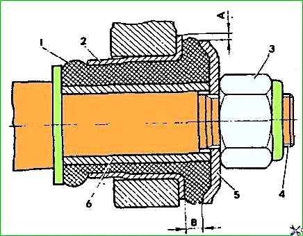
- - measure the radial displacement A (Fig. 2) of the outer bushing 2 relative to the inner bushing 6 and the distance B between the thrust washer 5 and the outer end of the outer bushing 2.
The rubber-metal hinges of the upper and lower arms are subject to replacement:
- - in case of ruptures and one-sided "bulging" of the rubber;
- - in case of undercutting and wear of the rubber at the ends of the hinges;
- - if the radial displacement "A" of the outer bushing relative to the inner one exceeds 2.5 mm;
- - if the dimension B does not fit within the limits of 3-7.5 mm.
If the dimension B is outside the specified limits, the correct pressing of the rubber-metal hinge into the socket should be checked lever.
Check the clearance in the upper ball joints in the following order:
- - place the car on a flat horizontal surface with a hard surface;
- - lift the right (left) front part of the car and remove the wheel;
- - place a wooden block 230 mm high under the lower arm, closer to the ball pin, and lower the car onto it;
- - make sure that the resin does not protrude from the sprue hole of the upper ball pin housing; if necessary, clean it with a file to avoid errors in measurement;
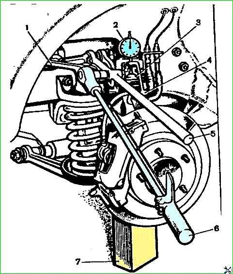
- - fasten bracket 4 (Fig. 3) of the device indicator to the upper end of the steering knuckle;
- - install indicator 2 in the center of the sphere of housing 3 of the ball pin with a slight preliminary compression, and then align the zero division of the indicator scale with the arrow;
- - fasten the forked lever 5 with a length of 0.7 m to the upper arm of the front suspension;
- - create a load of 196 N m (20 kgf m) in the vertical direction with a torque wrench 6 (at the end of the forked lever 294 N), first by pressing in and then by pulling the ball pin out of the joint housing;
- - record the corresponding maximum deviations of the indicator arrow;
- - calculate the value of the gap in the upper ball joint, adding up the values of deviations from the zero position;
- - the total indicator readings should not exceed 0.8 mm.
")

")
")
")
")
")
")
")