If the engine does not idle, one of the reasons may be a failure of the solenoid valve
Let's look at how the solenoid valve control system works.

The carburetor solenoid valve control unit turns off the valve (interrupts the fuel supply) when the crankshaft rotation speed increases to 2100 rpm –1 and turns on when the rotation speed decreases to 1900 rpm –1 if the carburetor limit switch is shorted to ground (the gas pedal is released).
When the gas pedal is pressed (the switch is open), the valve is turned on regardless of the crankshaft speed (fuel is supplied).
Power is supplied to the control unit only when the ignition is on, so when the ignition is turned off, the valve is also turned off (regardless of the position of the carburetor limit switch), which prevents the engine from operating with self-ignition (the solenoid valve is normally closed).
To check the operation of the control unit, we connect a voltmeter in parallel with the winding of the solenoid valve (the operation of the valve can also be determined by its knocking, without connecting a voltmeter).
Disconnect the wire from the carburetor limit switch and short it to ground.
Start the engine and, gradually increasing the crankshaft speed, monitor the voltmeter readings.
After starting the engine, the voltmeter should show at least 10 V (valve is open), and at a speed of about 2100 min –1 the voltage should drop sharply to a value of no more than 0.5 V (valve is closed) .
After this, we slowly lower the engine speed, about 1900 min –1 the voltage should increase abruptly to its previous value (valve open).
Set the speed within 2200–2300 min –1 (valve closed) and disconnect the carburetor limit switch wire from ground - the valve should open.
Removing the carburetor solenoid valve control unit
Turn off the ignition.
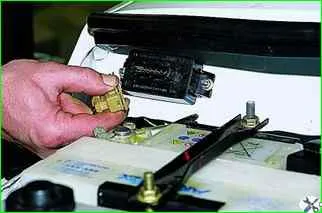
Disconnect the block from the carburetor solenoid valve control unit.
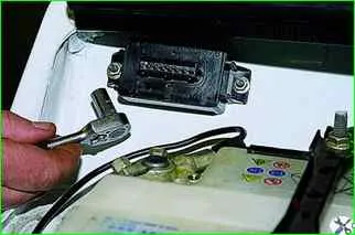
Using an “8” socket, unscrew the two nuts securing the block to the front panel
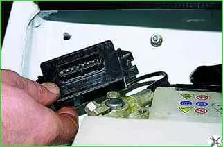
Remove the block
Install the control unit in reverse order.
Removing and checking the solenoid valve
Remove the air filter housing (see Removing the air filter housing).
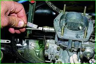
Remove the wire from the solenoid valve.
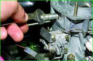
Using a 13mm wrench, unscrew the solenoid valve and remove it along with the idle jet and the rubber sealing ring in the cup.

If necessary, remove the O-ring and cup.
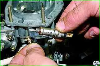
Remove the jet.
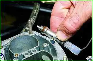
Check the serviceability of the solenoid valve and its circuit.
To do this, put the removed wire on the valve terminal and, turning on the ignition, press the valve body against the carburetor - the needle should click into the valve, and when the voltage is removed (remove it from the body), it should return to its original position without jamming.
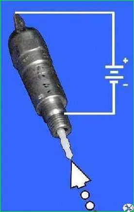
To check the serviceability of the valve itself, we connect its terminal with a wire to the “plus” of the battery, and the body to the “minus”.
If the needle does not retract, the valve is faulty
Install in reverse order.
The valve should not be over-tightened (it must be tightened “by hand”; if over-tightened, the valve will not work).
Checking the forced idle economizer limit switch
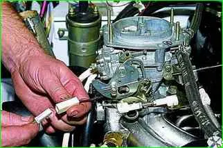
Disconnect the limit switch wire connector
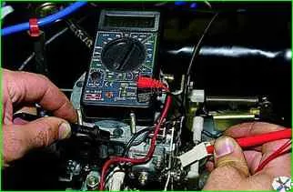
Using an ohmmeter we measure the resistance between the contact of the limit switch wire and the vehicle ground
With the throttle valve closed (the gas pedal is released), the device should show a resistance of about zero ohms, with the throttle valve open (the pedal is pressed) - infinity.


