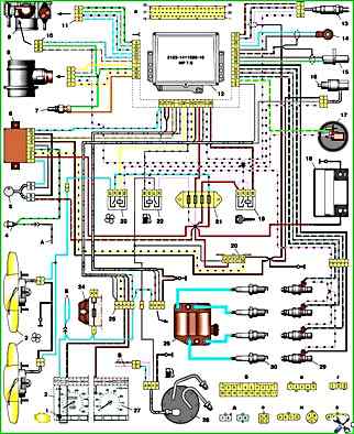
Connection diagram of the VAZ-21214 engine management system with distributed fuel injection under Euro-2 toxicity standards with controller 2123-1411020-10 (MR 7.0 type) on VAZ-21214 vehicles
1 – engine control system warning lamp; 2 – instrument cluster (fragments); 3 – electric fans of the engine cooling system; 4 – courtesy light switch, located on the driver’s door pillar; 5 – status indicator of the car anti-theft system; 6 – control unit of the automobile anti-theft system; 7 – coolant temperature sensor; 8 – air flow sensor; 9 – throttle unit; 10 – block connected to the throttle position sensor; 11 – block connected to the idle speed regulator; 12 – controller; 13 – oxygen concentration sensor; 14 – knock sensor; 15 – crankshaft position sensor; 16 – speed sensor; 17 – adsorber; 18 – battery; 19 – main relay; 20 – diagnostic block; 21 – fuse block for the engine control system; 22 – relay for turning on the electric fuel pump; 23 – relay for turning on electric fans; 24 – main car fuse box (fragment); 25 – block connected to the additional wiring harness*; 26 – ignition module; 27 – tachometer; 28 – electric fuel pump with fuel level sensor; 29 – nozzles; 30 – spark plugs; A – rear wiring harness wire connected to switch 4; B – wires connected to plug “1” of fuse block 24 (one wire goes to plug “15” of the ignition switch, and the other to plug “85” of the ignition relay); B – rear wiring harness wires connected to the fuel level indicator. The order of conditional numbering of plugs in the blocks: a – controller; b – control unit of the automobile anti-theft system; c – air flow sensor; g – speed sensor; d – indicator of the state of the automobile anti-theft system; e – electric fuel pump and oxygen concentration sensor; g – throttle pipe; h – ignition module. * Gray wires in block 25 – vehicle speed signal output, yellow-red wire – fuel consumption signal output (for the trip computer).


