We carry out the work on an inspection pit or lift
We remove the hood and spare wheel.
We dismantle the spare wheel supports.
We disconnect the tip of the "negative" cable from the battery.
We drain the oil and coolant from the engine.
We remove the radiator (in this case, on the VAZ-21213 we remove the fan casing, and on the VAZ-21214 - the electric fans).
We remove the thermostat with the cooling system hoses.
We disconnect the coolant inlet and outlet hoses from the heater radiator pipes.
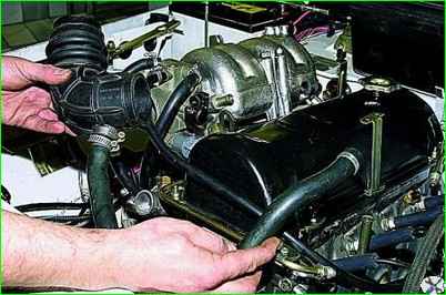
We remove the air filter housing (on an injection engine, we remove the housing with the mass flow sensor air).
Disconnect the throttle valve drive cable from the throttle assembly and the receiver of the injection engine.
Disconnect the air and throttle valve drives from the carburetor of the VAZ-21213 engine.
Dismantle the generator and starter.
Disconnect the inlet pipe from the exhaust manifold and gearbox.
Disconnect the brake booster hose from the engine.

Disconnect from the throttle assembly injection engine air supply and crankcase ventilation hoses, as well as the adsorber purge hose.
On the VAZ-21213 engine, disconnect the fuel supply hose from the fuel pump, and the drain hose from the carburetor.

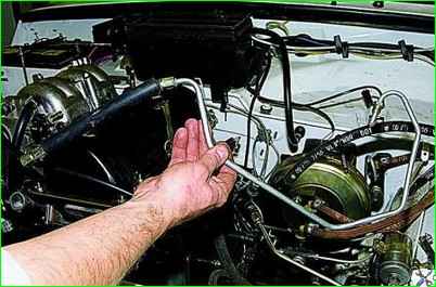
On the VAZ-21214 engine, disconnect the fuel drain hose from the fuel pressure regulator tube, and the fuel supply tube with the hose from the fuel rail and fuel filter (gradually releasing the fuel pressure in the system)
On the VAZ-21214 engine, remove the ignition module and disconnect the “ground” wire from the camshaft drive cover mounting stud; connectors of the engine wiring harness from the idle speed control valve, fuel rail, knock sensors, crankshaft and throttle position, coolant temperature (two sensors), oil pressure.

On the VAZ-21213 engine, disconnect the connectors of the engine wiring harness from the carburetor, ignition distributor sensor, oil pressure and coolant temperature sensors.
Move the wiring harnesses to the side.
Disconnect the central high-voltage wire from the distributor sensor cover ignition.
Unscrew the nuts securing the left and right powertrain mount cushions to the front suspension crossmember brackets.
Remove the center steering rod.
Disconnect the front axle gearbox mounts to the engine brackets.
Unscrew the bolts securing the clutch housing cover to its lower part and the bolts securing the clutch housing to the cylinder block.
To avoid damaging the clutch slave cylinder when dismantling the engine, disconnect the cylinder from the clutch housing (without disconnecting the hydraulic drive) and move it to the side on a hose.
The execution of these operations is described in the relevant articles.
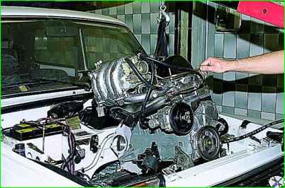
Secure the lifting device cable to the engine: on the right side - by the front eye; on the left side - by the rear bracket of the cylinder block, to which the front axle gearbox was attached.
Lifting the engine, we remove the studs of the cushions of the left and right supports of the power unit from the holes in the crossmember brackets.
Then we move the engine forward to remove the end of the primary shaft of the gearbox from the bearing located in the crankshaft flange and from the hub of the driven disk of the clutch.
We remove the engine from the engine compartment, complete with clutch and side supports of the power unit.
We install the engine on the car in the reverse order of removal.
When connecting the engine to the gearbox, the primary shaft of the gearbox must enter the splines of the driven disk of the clutch.


