If necessary, the engine piston group can be dismantled on the vehicle without removing the engine
We carry out the work on an inspection pit or lift.
We remove the engine oil pan (see Removing the oil pan and engine oil pump on a vehicle).

Using a 14 mm socket, we unscrew the two connecting rod cap fastening nuts (the piston should be in NMT).

Using a plastic-headed hammer (or a soft-metal-headed hammer), lightly tap the side surfaces of the cover to loosen its fit on the connecting rod bolts.

Remove the connecting rod cover.

Move the connecting rod up.

By resting the wooden handle of the hammer against the slot of the lower connecting rod head, push the connecting rod up until the piston exits the cylinder and remove the piston with the connecting rod assembly.

Similarly, dismantle the pistons with connecting rods of other cylinders.
Clamp the connecting rod in a vice with soft metal jaw pads.


Using your fingers, carefully (without applying much force) release the upper compression rings and remove the upper compression ring.

Remove the lower compression ring in the same way

Removing two oil ring discs.

Removing the oil scraper ring expander.

To remove the piston from the connecting rod, use a screwdriver to pry the piston pin retaining ring and remove it from the piston ring groove.

In the same way, remove the second pin retaining ring.

After moving the piston pin, we remove it from the hole in the piston.

Remove the piston from the upper head of the connecting rod.
If some parts of the connecting rod and piston group are not damaged and slightly worn, they can be used again.
Therefore, when disassembling, mark the parts so that they can be installed in the old cylinder.
Checking and assembling the connecting rod and piston group
Clean the bottom of the piston from carbon deposits with a scraper (can be made from an old file).
Clean the grooves for the piston rings from carbon deposits, using a piece of an old compression ring, rotating it.
Inspect the pistons, connecting rods, covers: there should be no cracks on them.
Inspect the liners.
If you find scratches, scoring and delamination on the working surface antifriction layer, replace the liners with new ones.

Measure the piston diameter in a plane perpendicular to the piston pin axis, at a distance of 52.4 mm from the piston bottom.
Based on the measurement results, determine the gap between the piston and the cylinder and, if necessary, select new pistons for the cylinders.

The calculated clearance between the piston and the cylinder (for new parts) is 0.05–0.07 mm.
It is determined by measuring the cylinders and pistons and is ensured by installing pistons of the same class as the cylinders.
The maximum allowable clearance (with worn parts) is 0.15 mm.
If the clearance of a used engine exceeds 0.15 mm, it is necessary to match the pistons to the cylinders: the clearance should be as close as possible to the calculated one.
Insert a pin lubricated with engine oil into piston boss hole.
The pin rotates freely in the piston bosses and in the upper head of the connecting rod.
By outer diameter, the pins are divided into three categories through 0.004 mm.
The category is indicated by paint on the end of the pin:
- 1st (blue mark) – 21.982–21.986 mm;
- 2nd (green mark) – 21.986–21.990;
- 3rd (red mark) – 21.990–21.994.
The pin should fit tightly, but without jamming, into the holes of the boss and connecting rod from the force of the thumb.

Turn the piston with the pin axis vertical. The pin should not fall out of the boss.
Replace a pin that falls out of the boss with another one of the next category.
If the piston has a pin of the third category, replace the piston with the pin.

Check the height clearance between the grooves in the piston and the rings with a flat feeler gauge, inserting the ring into the corresponding groove
The nominal (calculated) clearance is:
- – for the upper (first) compression ring 0.04–0.07 mm;
- – for the second compression ring 0.03–0.06 mm;
- – for the oil scraper ring 0.02–0.05 mm.
Maximum permissible clearances during wear – 0.15 mm.

Check the clearance in the lock with a flat feeler gauge rings, installing the ring into the cylinder to a depth of about 50 mm

To install the ring without distortion, push the ring into the cylinder with the piston
The gap should be 0.25–0.45 mm for all new rings.
The maximum allowable gap for wear is 1.0 mm.
If the gap is insufficient, file down the mating surfaces of the ring.
If the gap exceeds the permissible limit, replace the ring.

Pistons are selected for cylinders by class.
The cylinder diameter class, designated by letters, is stamped on the lower plane of the cylinder block (the plane of the oil pan mounting).

The piston skirt diameter classes and the piston pin holes are marked on its bottom
When assembling the connecting rod and piston group, it is necessary that the piston pin, lubricated with engine oil, enters the piston or connecting rod hole with the force of the hand and does not fall out of them when the pin is in a vertical position.
(Do not confuse with the assembly of the piston rod and piston group on a classic, where heating is used connecting rod when pressing in the piston pin!).

The arrow on the bottom of the piston when installing it in the cylinder should be directed towards the camshaft drive.
Put the piston on the connecting rod, making sure that the hole for the pin matches the hole in the upper head of the connecting rod.
Using your hand, push the pin lubricated with engine oil into the holes of the piston and connecting rod
If you need to replace the pistons, you need to check the weight of the pistons.
The weight of the pistons should not differ from each other by more than ± 2.5 g.

They can be adjusted by weight by removing metal in the place shown on both sides of the piston.
The depth of metal removal should not exceed 4.5 mm, counting from the nominal piston height of 59.4 mm.
In width, metal removal is limited to a diameter of 70.5 mm.

Use a bore gauge to measure the inner diameter Dв of the connecting rod seat with the cover.
Before measuring, tighten the connecting rod bolt nuts to a torque of 43.32-53.51 Nm (4.42-5.4 kgf m)
Insert retaining rings into the piston boss grooves and additionally lubricate the pin with engine oil through the holes in the piston bosses.
To check the gap in the piston ring lock, insert the ring into the cylinder and align the ring with the piston bottom.
Using a set of flat feeler gauges, check the gap in the piston ring lock.

Lubricate the grooves on the pistons with engine oil.
Install the rings on the pistons. Install the lower compression ring with the groove ("scraper") facing down
If the ring near the lock has a mark "TOP" or "TOP", then install the ring with the mark facing up.
The rings should rotate freely in the grooves without jamming. We arrange the rings as follows:
- - the lock of the upper compression ring is oriented at an angle of 45° to the axis of the piston ring;
- - the lock of the lower compression ring is oriented at an angle of 180° to the axis of the lock of the upper ring;
- - the lock of the oil scraper ring is oriented at an angle of 90° to the axis of the lock of the upper compression ring (the joint of the expander is located on the side opposite the lock).
Checking the connecting rod for deformation
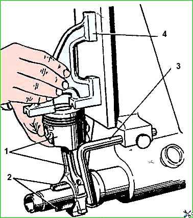
Before installing the assembled connecting rod and piston group on the engine, it is necessary to check the parallelism of the group axes with a special device or similar, shown in the figure.
To check, center the connecting rod lower head (without liners) on retractable knives 2, and install gauge 4 on the piston bottom.
Using a set of feeler gauges, check the gap between the vertical plate of the device and the vertical plane to caliber at a distance of 125 mm from the corner or the upper end of the caliber (depending on how it touches the plate - the corner or the upper end).
The gap should not exceed 0.4 mm. If the gap is larger, replace the connecting rod.
Before installing the connecting rod and piston group parts, lubricate the cylinders, pistons with rings, and connecting rod bearings with engine oil.

Before installing the piston in the cylinder, put an adjustable mandrel on the piston and, tightening the mandrel, compress the piston rings.

We install the piston with the connecting rod into the cylinder. Using the hammer handle as a support against the piston bottom, push it into the cylinder.

When installing the connecting rod cap, the numbers on the connecting rod and cap must match and be located on the same side of the connecting rod.
Insert the connecting rod bolts (if removed) and liners into the connecting rods, aligning the installation tab with the recess on the connecting rod

Tighten the connecting rod mounting nuts to a torque of 43.32-53.51 Nm (4.42-5.4 kgf m)
Assemble all parts and components in the reverse order of disassembly.
")

")
")
")
")
")
")
")