We have considered engine disassembly in the article – “Engine Disassembly”
After disassembly, thoroughly wash the parts with kerosene, blow and dry them with compressed air (especially the oil channels of the parts).
Inspect the block, especially carefully – the crankshaft supports.
Cracks in any places of the block are not allowed.
If there is a suspicion of cracks in the block (coolant got into the crankcase or oil into the coolant), check the tightness of the block on a special stand.
Carry out the check in repair shops with the appropriate equipment.
Inspect the cylinders from both sides.
Scratches, scoring and cracks are not allowed.
When inspecting the cylinders, we recommend illuminating the cylinder mirrors with a portable lamp – when in this case, the defects are much more visible.
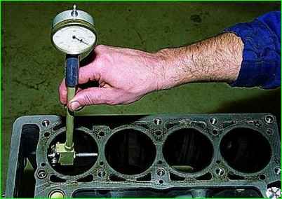
To determine cylinder wear, use a bore gauge to measure the cylinder diameter in four zones and two planes (parallel and perpendicular to the crankshaft axis).
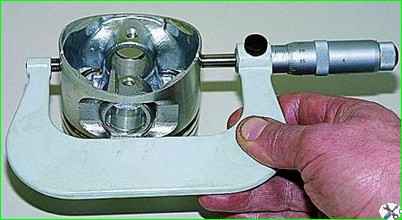
To determine the wear of the piston skirt, use a micrometer to measure the diameter in a plane perpendicular to the axis of the piston pin, at a distance of 55 mm from the piston bottom.
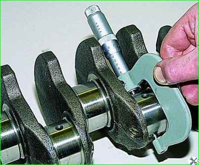
Using a micrometer, we measure the diameters of the connecting rod journals.
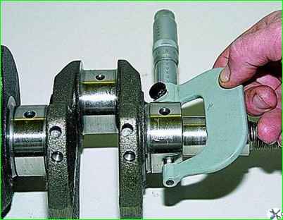
Using a micrometer, we measure the diameters of the main journals of the crankshaft.
Grind the crankshaft journals to the nearest repair size if they are worn or ovality is greater than 0.03 mm, and also if there are burrs and scratches on the journals.
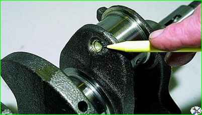
After grinding the crankshaft journals, it is necessary to remove the oil channel plugs, thoroughly rinse the channels to remove any remaining abrasive and blow them out with compressed air.
Assemble the engine in the reverse order.
Install new crankshaft bearing shells nominal or repair size (after grinding the journals).
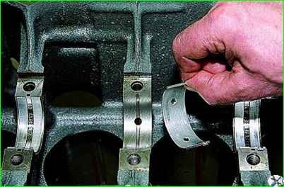
In the first, second, fourth and fifth supports of the cylinder block, we install the upper liners of the main bearings with grooves, and in the third support - an liner without a groove on the inner surface (the same as in the main bearing caps).
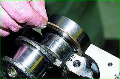
Lubricate the main bearing shells with engine oil and place the crankshaft in the supports.
Insert the thrust half rings lubricated with engine oil into the grooves of the fifth support.
Install a steel-aluminum half ring on the front side of the fifth support, and a metal-ceramic half ring (yellow) on the back side.
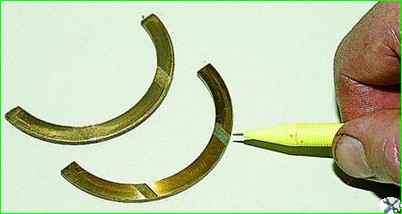
The surfaces of the half rings with an antifriction coating (grooves are made on them) must face the thrust surfaces of the crankshaft.
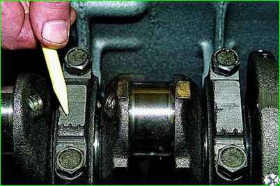
We install the main bearing caps in accordance with the marks applied to their outer surface (the count is carried out from the side of the camshaft drive).
When om locks of the upper and lower liners of each main bearing must be located on the same side.
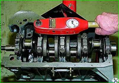
Tighten the main bearing cap bolts to a torque of 68.31-84.38 Nm (6.97-8.61 kgf m).
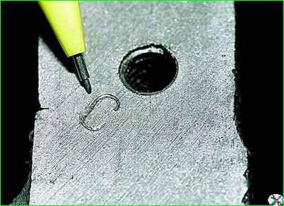
Pistons for cylinders are selected by class.
The cylinder diameter class, designated by letters, is stamped on the lower plane of the cylinder block (the plane of the oil pan mounting).
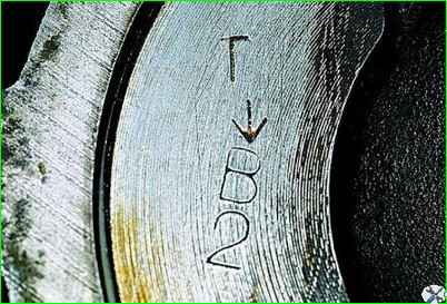
Piston skirt diameter classes and piston pin holes are marked on its bottom
The arrow on the piston bottom when installing it in the cylinder should be directed towards the camshaft drive.
When assembling the connecting rod and piston group, it is necessary that the piston pin, lubricated with engine oil, enters the piston or connecting rod hole with hand force and does not fall out of them when the pin is in a vertical position.
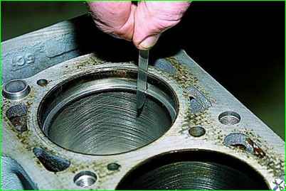
To check the gap in the piston ring lock, insert the ring into the cylinder and align the ring with the piston bottom.
Using a set of flat feeler gauges, check the gap in the piston ring lock.
Lubricate the grooves on the pistons with engine oil. Install the rings on the pistons.
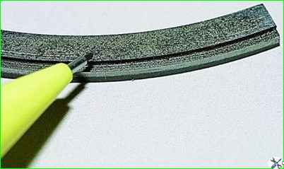
Install the lower compression ring with the groove ("scraper") facing down
If the ring near the lock has a mark "TOP" or "TOP", then install the ring with the mark facing up.
The rings should rotate freely in the grooves without jamming.
Arrange the rings as follows way:
- - the upper compression ring lock is oriented at an angle of 45° to the piston ring axis;
- - the lower compression ring lock is oriented at an angle of 180° to the upper ring lock axis;
- - the oil scraper ring lock is oriented at an angle of 90° to the upper compression ring lock axis (the expander joint is located on the side opposite the lock).
Before installing the rod bearing parts, lubricate the cylinders, pistons with rings and connecting rod bearings with engine oil.
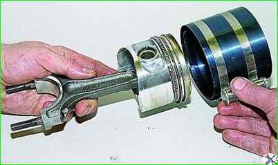
Before installing the piston in the cylinder, put an adjustable mandrel on the piston and, tightening the mandrel, compress the piston rings.
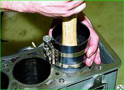
Install the piston with the connecting rod in the cylinder. Using the hammer handle as a support against the piston bottom, push it into the cylinder.
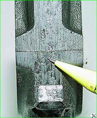
When installing the connecting rod cap, the numbers on the connecting rod and cap must match and be located on the same side of the connecting rod.
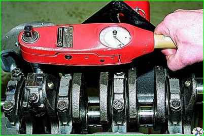
Tighten the connecting rod mounting nuts to a torque of 43.32-53.51 Nm (4.42-5.4 kgf m)
Further assembly is carried out in the reverse order of disassembly.
Replace the sealing gaskets and oil seals with new ones.
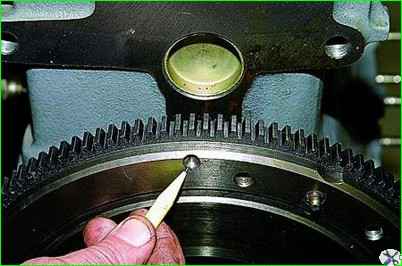
When installing the flywheel, orient it so that the installation (conical hole), located on the rear plane of the flywheel next to the toothed ring, is located opposite the connecting rod journal of the fourth cylinder.


