The intermediate shaft transmits torque from the secondary shaft of the gearbox to the input shaft of the transfer case
It consists of an elastic coupling, a flange and a constant velocity joint.
The intermediate shaft is centered on the secondary shaft of the gearbox with a rubber bushing.
The elastic coupling allows torque to be transmitted with minor changes in the angle between the shafts of the gearbox and transfer case, protects transmission parts from dynamic impacts and reduces noise and vibration of the cardan transmission during operation.
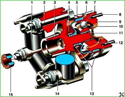
Intermediate shaft VAZ-2121: 1 - elastic coupling; 2 - elastic coupling fastening bolt; 3 - elastic coupling flange; 4 - protective cover; 5 - casing; 6 - separator; 7 - ball; 8 - stud for fastening the hinge housing to the transfer case flange; 9 - hinge housing; 10 - plug; 11 - retaining ring; 12 - hinge cage; 13 - clamps; 14 - balancing washer; 15 - centering sleeve
The elastic coupling consists of six steel liners connected by rubber bridges.
Due to its elasticity, the coupling dampens jerks in the vehicle transmission.
The elastic coupling is attached to the secondary shaft flange with three bolts passed through the holes in the liners.
The other three holes are used to attach the coupling to the flange on the intermediate shaft.
Balancing washers are located under the nuts of the bolts.
When disassembling, we mark their location so that we can later install them in their original places.
In order not to disturb the balance, we mark the relative positions of other parts of the intermediate shaft.
A constant-angle joint is put on the splined end of the elastic coupling flange. speeds.
Its design is similar to the outer hinge of the front wheel drive.
The hinge is secured from displacement by a retaining ring located in the groove on the flange shaft.
The hinge is protected from dirt by a rubber corrugated cover and a plastic plug in the rear end of the hinge housing.
The cover is secured to the flange shaft and the hinge housing with special clamps with locks.
There is a protective plastic cover under the large clamp (on the hinge housing).
On the first VAZ-2121 models, a crosspiece was installed instead of a constant velocity joint.
Removing the intermediate shaft
Remove the transfer case assembly with the intermediate shaft (see. Transfer case removal).

Holding the shaft from turning with a screwdriver, use a 13 mm wrench to unscrew the four nuts securing the intermediate shaft to the transfer case flange.

Removing the intermediate shaft.
Install the intermediate shaft on the transfer case in the reverse order.

Before installing the intermediate shaft assembly with the transfer case, check the condition of the rubber centering sleeve located on the flange of the secondary shaft of the gearbox.
Disassembling the intermediate shaft shaft
We disassemble the intermediate shaft to replace the elastic (rubber) coupling or constant velocity joint.

We mark the location of the coupling relative to the flange, as well as the number and location of the balancing washers relative to the coupling.

Holding the bolts from turning with a 19 mm wrench, unscrew the three nuts with a head of the same size.

Disconnect the coupling and flange.

Turning the hinge, remove the bolts from the holes in the flexible coupling flange.

Prying it off with a screwdriver, remove the plastic plug.

Squeezing the clamp with sliding pliers, remove it.

Move the plastic cover with a screwdriver

Remove the rubber protective boot from the constant velocity joint housing

Place the joint housing on the open jaws of a vice and, striking the end face of the flexible coupling flange with a soft metal punch, knock out the flange.

Disconnect the joint and the flange.

Pull the plastic cover off the rubber boot.

Pull the rubber boot back, squeeze the clamp with sliding pliers and remove it

Removing the rubber protective cover

Prying it off with a screwdriver, remove the hinge retaining ring
Disassembling and assessing the condition of the hinge parts are similar to the corresponding operations described in the article - "Repair of drives front wheels".
We assemble the intermediate shaft in the reverse order.
We put 20 cm 3 of SHRUS-4 grease into the disassembled or new joint.
Before connecting the joint to the flange of the elastic coupling, we install a small clamp of the rubber protective boot.

We press the joint onto the flange, striking through a section of pipe on the joint cage

Before installing the rubber coupling, we compress it with a clamp
We place the used coupling according to the marks relative to the flange.
We place the old balancing washers according to the marks relative to the coupling.
When installing a new coupling, it may be necessary to balance the shaft assembly.
Tightening torques of the intermediate shaft
Nut of the bolt for fastening the elastic coupling to the flanges M12x1.25 - 57.8-71.5 Nm (5.9-7.3 kgf m)
Nut for fastening the hinge housing to the flange of the transfer case drive shaft M8 - 27.4-34.3 Nm (2.8-3.5 kgf m)