Checking the wheel alignment angles is mandatory if suspension components that may change the wheel alignment were replaced or repaired
Check and adjust the wheel alignment angles on the vehicle under a static load of 3140 N (320 kgf) (four people and 40 kg in the trunk).
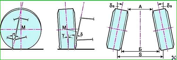
Wheel alignment angles: t – longitudinal inclination angle of the steering axis; m – wheel center; γ – camber angle; δ – transverse tilt angle of the steering axis; m – wheel center; B–A – front wheel toe-in; A and B – distance (mm) between front and rear wheels; δ s – front wheel toe-in; s – track
It is recommended that the front wheel alignment angles be checked and adjusted at a service station.
The vehicle is placed on a horizontal platform and loaded in accordance with the manufacturer's recommendations. (Checking and adjusting the angles on an unloaded vehicle is acceptable, but will provide less accurate results.)
Before doing this, make sure that the tire pressure is correct, the tread wear on the left and right wheels is approximately the same, there is no play in the bearings and steering, and the wheel rims are not deformed (radial runout is no more than 0.7 mm, axial runout is no more than 1 mm).
The wheel alignment angles should have the following values:
- - camber -0° 30´ ± 20´
- - longitudinal angle of inclination of the steering axis 3° 30´ ± 30´
- - toe-in -3 ± 1 mm.
Before adjusting the wheel alignment angles, check:
- - air pressure in tires;
- - axial clearance in the front wheel hub bearings;
- - serviceability of shock absorbers (no jamming of rods);
- - radial and axial runout of tires;
- - clearance in the suspension ball joints;
- - free play of the steering wheel.
Eliminate any detected faults and make the necessary adjustments.
After installing the car on the stand, immediately before checking the angles, it is necessary to “squeeze” the car suspension, applying 2-3 times a force of 392-490 N (40-50 kgf) (directed from top to bottom), first on the rear bumper, and then on the front.
The order of checking and adjusting the wheels should be as follows:
- 1. Angle of longitudinal tilt of the steering axis
- 2. Camber angle
- 3. Toe-in
Pivot Angle
Pivot angle is the angle between the vertical and the projection of the line passing through the centers of the ball joints onto a plane parallel to the longitudinal axis of the vehicle.
It helps stabilize the steered wheels in the direction of straight-line movement.
This angle is adjusted by changing the number of adjusting washers on the upper arm axle mounting bolts.
When washers are removed from the rear bolt or added to the front bolt, it increases; when they are replaced, it decreases.
Symptoms of an angle deviation from the norm: vehicle pull to the side while driving, different steering wheel forces in left and right turns, one-sided tire tread wear.
If the angle does not match the data given above during checking, it is necessary to change the number of adjusting washers installed between the upper arm axle and the bracket crossbars.
Change in camber angles and longitudinal tilt of the steering axis when changing the number of 0.75 mm thick washers on the upper arm axle mounting bolts
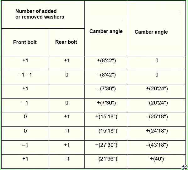
Data are given for 0.75 mm thick washers. Plus - adding a washer, minus - removing a washer.
To adjust the longitudinal tilt angle of the steering axis:
- unscrew the nuts securing the axle of the upper arm of the front suspension and move the washers from one bolt to the other until the normal angle value is obtained.
The longitudinal tilt angle of the steering axis increases when the washers are moved from the rear bolt to the front and decreases when they are moved back;
- tighten the nuts with a torque wrench and check the correctness of the longitudinal tilt angle of the steering axis.
Front camber angle
The camber angle of the wheels is the angle between the plane of rotation of the wheel in the "straight ahead" position and the vertical.
It promotes the correct position of the rolling wheel when the suspension is operating. The angle is adjusted by changing the number of washers on the bolts securing the axle of the upper arm.
To reduce camber, an equal number of washers are taken from both bolts (packs of washers of equal thickness), to increase - add.
At the factory, one 3 mm thick washer is placed on each bolt, the rest of the washers are 0.75 mm. If necessary, remove thick washers.
If all washers are removed, but the angles cannot be adjusted, check the condition of the rubber-metal hinges and the suspension cross member: the distance between the outer surfaces of the cross member brackets near the bolts for fastening the upper arm axles should be 736±1.5 mm.
If this is not the case, replace the cross member, check the body geometry at a service station.
If the camber angle deviates significantly from the norm, the car may be pulled away from straight-line movement and the tread may wear on one side.
If the camber angle differs from the norm, it must be adjusted by changing the number of washers installed between the upper arm axle and the cross member bracket.
To decrease the camber angle, remove the same number of washers from both bolts, and to increase it, add more.
Front wheel alignment
Wheel alignment is the angle between plane of rotation of the wheel and the longitudinal axis of the vehicle. Sometimes this angle is measured as the difference between the distances A and B (see figure).
Toe-in helps to ensure the correct position of the steered wheels at different speeds and angles of rotation of the vehicle.
The angle is adjusted by changing the length of the side steering rods by rotating the adjusting sleeves with the tightening clamps loosened.
Before adjustment, the steering arm is set to the middle position (the steering wheel spokes are horizontal).
Signs of deviation from the norm: strong sawtooth wear of the tires (even with small deviations), squealing tires when turning, increased fuel consumption due to high rolling resistance of the front wheels (the vehicle coasts much less than required).
If the toe-in value differs from the norm, then it is necessary to loosen the tightening clamps of the side rods and use a wrench 67.7813.9504 turn both couplings by the same amount in opposite directions; in this way, the couplings are screwed on or unscrewed and change the length of the lateral rods.
After completing the adjustment, install the clamping clamps with the slot facing backwards, with an acceptable downward deviation of 60° to the horizontal plane of the car.
When the nuts are tightened, the edges of the slots of the clamping clamps should not touch.
After adjusting the wheel alignment, check that the wheels and steering gear components do not touch adjacent suspension and body components.
To do this, turn the wheels in both directions until they stop, until the pitman arm rests against the steering gear housing mounting bolts.
")

")
")
")
")
")
")
")