Starter 35.3708 – four-brush DC electric motor with mixed excitation and with an electromagnetic two-winding traction relay
In the starter housing, four poles with field windings are secured with screws: three series (series) and one shunt (parallel). The body together with the covers are tightened with two bolts.
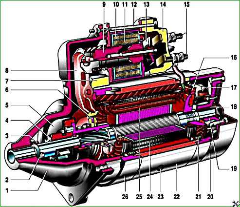
Starter 35.3708 assembled: 1 - cover on the drive side; 2 - retaining ring; 3 - restrictive ring; 4 - drive gear; 5 - overrunning clutch; 6 - drive ring; 7 - rubber plug; 8 - drive lever; 9 - relay anchor; 10 - holding winding of the traction relay; 11 - pull-in winding of the traction relay; 12 - relay coupling bolt; 13 - contact plate; 14 - relay cover; 15 - contact bolts; 16 - collector; 17 - brush; 18 - armature shaft bushing; 19 - cover, from the collector side; 20 - casing; 21 - shunt coil of the stator winding; 22 - body; 23 - stator pole fastening screw; 24 - anchor; 25 - armature winding; 26 - intermediate ring
Anchor – with end commutator.
The rear end of the armature shaft rotates in a cermet bushing pressed into the cover on the commutator side, and the front end rotates in a bushing pressed into the cover on the drive side.
A freewheel (overrunning clutch) with a drive gear is installed on the drive shaft.
It transmits torque in only one direction - from the starter to the engine, separating them after the engine starts.
This is to protect the starter armature from damage due to excessive speed.
The traction relay is used to engage the drive gear with the flywheel gear of the engine crankshaft and turn on the power to the starter motor.
When the ignition key is turned to the “starter” position, voltage through an additional relay type 113.3747-10 is supplied to both windings of the traction relay (retracting and holding).
After the contacts of the traction relay are closed, the retractor winding is turned off.
The response voltage of the traction relay should be no more than 9 V at (20±5)°C.
If this is not the case, there is a problem with the relay or drive.
The serviceability of the drive is determined by inspection after disassembling the starter. The faulty relay is replaced.
Technical characteristics of starter 35.3708
Rated power - 1.3 kW
Current consumption at maximum power, no more than 290±10 A
Current consumption in the inhibited state, no more than 550 A
Current consumption in idle mode, no more than 60 A
Checking and repairing starter 35.3708
We clean the starter from dirt and install it on a workbench.

Using a 13mm wrench, loosen the nut securing the wire to the traction relay.

Disconnect the wire tip.

To check the traction relay, apply +12 V to the relay output, minus to the body, and connect an ohmmeter to the contact bolts.

In this case, for a working relay, the armature should move the overrunning clutch into the window of the front cover, and the contact bolts should close.
Replace the faulty traction relay with a new one.

Use a slotted screwdriver to unscrew the three screws.

Remove the traction relay

We remove the rod with the spring from the relay body. We install a new traction relay in the atomic sequence

To further disassemble the starter, use a Phillips screwdriver to unscrew the two screws.

Remove the cover.

To check the condition of the brushes, use a screwdriver to unscrew the screw securing the contact wire

Using a screwdriver to press out the spring, remove the brush. Use the same method to remove the three remaining brushes.
Brushes worn to a height of 12 mm or less are replaced.

Connecting an ohmmeter one by one to the terminals of the stator windings, we check them for short circuits to the housing and for interturn short circuits.
At the same time, make sure that the free terminals of the windings are insulated from the housing.

Using a screwdriver, remove the retaining ring.

Remove the washer from the shaft.

Use a 10mm wrench to unscrew the two coupling bolts

...and take them out

Disconnect the starter parts and remove the insulating tubes of the bolts
We check the condition of the collector and windings by external inspection. Charring of windings is not allowed.
If the collector is slightly burned, we clean its plates with fine abrasive sandpaper. In case of severe burning and wear, it is better to replace the anchor.
We remove scuffing and enveloping of metal from the bearings onto the journals of the armature shaft with the finest sandpaper, followed by polishing.

We use an ohmmeter to check the armature windings for a short circuit. We replace the faulty anchor.

Remove the rubber seal from the drive cover.

Remove the adjusting washer from the armature axis.

Unsplint the lever axis.

Knock out the axle with a beard

Remove the anchor with the drive.

Use a screwdriver to remove the drive lever.
The drive gear should rotate easily in one direction and not rotate in the other, and should not have chips or nicks on the leading part of the teeth.
We replace the worn gear or faulty overrunning clutch as an assembly.

Resting the armature shaft on a wooden block, use a 14mm wrench to knock the restrictive ring off the locking ring

Use a screwdriver to remove the retaining ring

Remove the restrictive ring and the overrunning clutch assembled with the drive gear from the shaft. We assemble the starter in the reverse order.

When installing the restrictive ring (on the locking ring), it is convenient to tighten it using sliding pliers. We blow out the housing and brush holder with compressed air.
Lubricate the drive ring and the plastic surfaces in contact with it with Litol-24.
Lubricate the bushings and screw splines of the armature shaft, as well as the overrunning clutch hub with engine oil.

Before connecting the cover to the starter housing, insert the coupling bolts into the corresponding holes.
If only one bolt was insulated, when assembling the starter, we put the insulating tube on the one that can touch the copper busbar connecting the starter stator windings.

To install the retaining ring, push the starter armature up through the cover sleeve on the drive side.