A starter 5722.3708 is installed on some of the engines of the VAZ-2121 car - a four-pole four-brush DC electric motor with excitation from permanent magnets, with a planetary gearbox, a roller freewheel clutch and a two-winding traction relay.
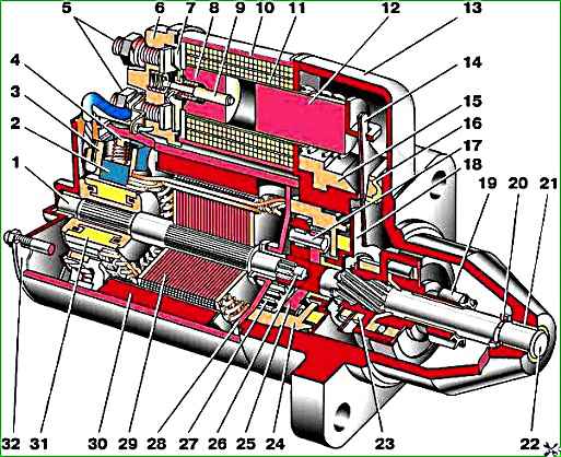
Starter 5722.3708 assembled: 1 - armature shaft; 2 - “positive” brush; 3 - brush holder; 4 - bracket; 5 - contact bolts; 6 - traction relay; 7 - contact plate; 8 - traction relay core; 9 - traction relay rod; 10 - holding winding; 11 - retractor winding; 12 - relay anchor; 13 - front cover; 14 - drive lever; 15 - lever bracket; 16 - gasket; 17 - planetary gear axis; 18 - drive shaft support with liner; 19 - overrunning clutch; 20 - restrictive ring; 21 - front cover bushing; 22 - drive shaft; 23 - outlet ring; 24 - gear with internal teeth; 25 - carrier; 26 - central (drive) gear; 27 - satellite; 28 - armature shaft support with liner; 29 - armature core; 30 - permanent magnet; 31 - collector; 32 - back cover with bushing
Figure 1 shows a cross-section of the starter.
Technical characteristics of starter 5722.3708
Rated power - 1.55 kW
Current consumption at maximum power, no more than - 375 A
Current consumption in the inhibited state, no more than - 700 A
Current consumption in idle mode, no more than - 80 A
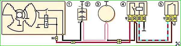
The starter connection diagram is shown in Figure 2.
Four permanent magnets are glued to the steel body of the starter; each is additionally secured from the inside with a flared aluminum bushing.
The starter housing and covers are secured with two studs.
The armature shaft rotates in two metal-ceramic liners installed in the cover and shaft support.
The torque from the armature shaft is transmitted to the drive shaft through a planetary gearbox, consisting of a central gear, three planetary gears, a carrier and an internal gear (epicyclic)
Disassembling the starter
We clean the starter from dirt and install it in a vice.

Use a 13mm wrench to unscrew the nut of the lower terminal of the traction relay.

Remove the wire.

Using a 8-point socket, unscrew the two bolts securing the traction relay and remove it.
Remove the traction relay anchor.

Use a 10mm wrench to unscrew the tie rod nuts.

Remove the stator together with the armature from the cover studs

Use a Phillips screwdriver to unscrew the two screws

Remove the back cover.

Remove the brush holder.

Remove the anchor.

Remove the central gear from the armature shaft

Remove the armature shaft support.

Take out the three planetary gears.

Use a soft metal drift to knock out the drive shaft

Remove it assembled with the drive shaft support and lever.

Remove the sealing gasket.
Install the drive shaft on a wooden stand.

We rest the jaws of the open-end wrench “14” on the restrictive ring and, hitting the key with a hammer, press the restrictive ring.


Pry up the locking ring with a screwdriver and remove it

Remove the restrictive ring.
Remove the drive assembly.

Use pliers to open the locking ring

Remove the locking ring

Remove the tapping ring with the washer.

To replace the brushes, pry off the plastic covers and the springs located under them.

Assemble the starter in reverse order.

Before installing the brush holder on the armature commutator, remove all four springs so that the brushes “go” into the guides.

Insert the armature with the brush holder on, installed springs and their covers into the stator
Assemble the starter in reverse order
After assembly, we check the functionality of the starter and install it on the engine.
")

")
")
")
")
")
")
")