The fuel system of the Niva injection engine consists of a fuel tank, an electric fuel pump, a fuel rail with injectors, a fuel pressure regulator, a throttle assembly, a fuel vapor recovery system, filters, and pipelines
The tank is stamped from lead-coated steel sheet, its upper and lower halves are welded together.
The filler neck is connected to the tank by two rubber hoses; the lower thick hose is used to fill the fuel, the upper (thin) one is used to remove displaced air when filling the tank with fuel.
The hoses are secured with clamps.
The tank cap is airtight.
Two fittings in the upper part of the tank (left and right) are used to ventilate the tank, they have plastic tubes connected to the separator.
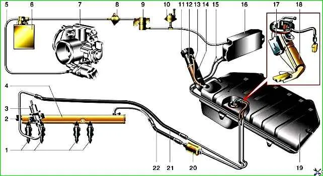
Scheme of the fuel system of the engine with distributed fuel injection VAZ-2121: 1 - injectors; 2 - fuel pressure control nipple cap; 3 - fuel pressure regulator; 4 - fuel rail; 5 - hose for sucking gasoline vapors from the adsorber; 6 - adsorber with electromagnetic valve; 7 - throttle assembly; 8 - two-way valve; 9 - gravity valve; 10 - safety valve; 11 - plug; 12 - filler pipe; 13 - fuel tank and filler pipe hose; 14 - filler pipe hose; 15 - separator hoses; 16 - separator; 17 - fuel level sensor; 18 - electric fuel pump; 19 - fuel tank; 20 - fuel filter; 21 - fuel drain line; 22 - fuel supply line
The separator is secured with self-tapping screws in a niche of the right rear part of the body. It is connected to the adsorber in the engine compartment by hoses and pipes.
A gravity and two-way valve are installed in the hose sections near the separator, as well as a tee connected to the fuel vapor release hose.
The latter comes out on the outside of the body near the filler neck, and a safety valve is installed in its section.
Fuel vapors from the tank partially condense in the separator, the condensate drains back into the tank.
The remaining vapors pass through the gravity and two-way valves and enter the adsorber.
The gravity valve prevents fuel from leaking out of the tank when the car rolls over, and the two-way valve prevents excessive pressure increase or decrease in the fuel tank.
In the adsorber, fuel vapors are absorbed by activated carbon.
The second nipple of the adsorber is connected by a hose to the throttle assembly, and the third – with the atmosphere.
When the engine is off, the latter is closed by an electromagnetic valve, and in this case the adsorber does not communicate with the atmosphere.
When the engine is started, the injection system controller begins to send control pulses to the valve at a frequency of 16 Hz.
The valve connects the adsorber cavity with the atmosphere and the sorbent is purged: gasoline vapors are sucked through the hose and the throttle assembly into the receiver and then into the engine cylinders.
The higher the air consumption of the engine, the longer the duration of the control pulses, the more intense the purging.
The fuel pump is electric, submersible, rotary, structurally combined with fuel level sensors and its reserve remainder in the tank.
It is installed on studs in the upper part of the fuel tank.
The pump is turned on by command from the injection system controller (with the ignition on) through relay.
From the pump, fuel is supplied under pressure through hoses and pipes located under the bottom to the fine filter in the engine compartment and then to the fuel rail.
The fine fuel filter is non-separable, in a steel housing, with a paper filter element, located on the left side of the engine compartment.
There is an arrow on the filter housing that must match the direction of fuel flow.
The fuel rail is used to supply fuel to the injectors and is attached to the intake manifold.
It contains a fitting for monitoring the fuel pressure (on the side facing the engine shield) and a pressure regulator.
The pressure regulator changes the pressure in the fuel rail within the range from 2.8 to 3.2 bar (2.8–3.2 atm) depending on the vacuum in the receiver, maintaining a constant pressure difference between them.
This is necessary for precise dosing of fuel by the injectors.
The fuel pressure regulator is a fuel valve connected to a spring-loaded diaphragm. Under the action of the spring, the valve is closed.
The diaphragm divides the regulator cavity into two isolated chambers - "fuel" and "air". The "air" is connected by a vacuum hose to the receiver, and the "fuel" - directly to the ramp cavity.
When the engine is running, the vacuum, overcoming the resistance of the spring, tends to draw in the diaphragm, opening the valve.
On the other hand, fuel presses on the diaphragm, also compressing the spring inu.
As a result, the valve opens, and some of the fuel is released through the drain line back into the tank.
When you press the gas pedal, the vacuum behind the throttle valve decreases, the diaphragm closes the valve under the action of the spring, and the fuel pressure increases.
If the throttle valve is closed, the vacuum behind it is maximum, the diaphragm pulls the valve harder - the fuel pressure decreases.
The pressure difference is determined by the spring stiffness and the size of the valve opening, it is not subject to adjustment.
The pressure regulator is non-separable, if it fails, it is replaced.
The injectors are electromagnetic valves that pass fuel when voltage is applied and close under the action of the return spring when de-energized.
At the outlet of the injector there is a sprayer through which fuel is injected into the intake pipe.
The injectors are sealed in the rail with rubber rings, it is recommended to replace them each time the injector is dismantled.
The injectors are controlled by the injection system controller.
If there is a break or short circuit in the winding, the injector should be replaced.
If the injectors are clogged, they can be washed on a special service station stand without dismantling them.
The plastic air filter housing is installed in the rear right part of the engine compartment on three rubber holders.
The filter element is paper.
After the filter, the air passes through the mass air flow sensor and enters the intake hose leading to the throttle assembly.
The throttle assembly is attached to the receiver.
By pressing the gas pedal, the driver opens the throttle valve, changing the amount of air entering the engine, and therefore the combustible mixture - after all, the fuel supply is calculated by the controller depending on the air flow.
The composition of the mixture is regulated by the duration of the control pulse supplied to the injectors (the longer the pulse, the greater the fuel supply).
Fuel can be supplied "synchronously" (depending on the position of the crankshaft, while the injectors are turned on in pairs - for cylinders 1-4 and 2-3) and "asynchronously" (regardless of the position of the crankshaft, all injectors work).
The latter mode is used when starting the engine.
If the throttle valve is open more than 75% when the engine crankshaft is turned by the starter, the controller perceives the situation as a cylinder purge mode and does not issue pulses to the injectors, blocking the supply fuel.
This is done if there is a suspicion that the mixture is over-enriched (the engine is "flooded") and therefore it does not ignite.
If during purging the engine starts to run and its speed reaches 400 min –1 , the controller will turn on the fuel supply.
During engine braking, the controller leans the mixture to reduce the toxicity of exhaust gases, and in some modes it completely turns off the fuel supply.
The fuel supply is also turned off when the ignition is turned off, which prevents spontaneous combustion of the mixture in the engine cylinders (dieseling).
")

")
")
")
")
")
")
")