Transmission of torque to the drive axles is carried out by open-type cardan shafts (Fig. 1), each of which has a movable spline connection and two cardan joints
The design of the rear and front driveshafts is the same.
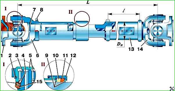
They differ only in length, and also in the fact that the rear propeller shafts have a thin-walled pipe 13 (Fig. 1), and the front ones are made of a combined pipe and shaft.
Drive shaft splines can be of two types - straight-sided or involute.
Maintenance of cardan shafts
Periodically check the tightness of the bolts securing the propeller shaft flanges to the transfer case flanges and the drive gear of the front and rear axles.
Check the clearances of the hinges and spline joints, lubricate them in accordance with the instructions in the lubrication table.
Tighten the flange mounting bolts as far as possible.
For lubrication, use a syringe with a special tip.
This tip fits onto the syringe and is included in the driver's tool kit.
Excessive lubricant should not be introduced into the splines, as it will be thrown out of the spline joint, which will lead to premature failure of the oil seals and may knock out the sliding fork plug.
The cardan shafts do not require any adjustments.
Repair of cardan shafts
The driveshafts are dynamically balanced.
Eliminate imbalance by welding plates at the ends of the shaft.
When using an individual repair method, install parts suitable for further work in their original places where they were worn in.
Before removal, mark such parts in any way that does not damage them (paint, punching, etc.).
To repair, remove the shaft from the vehicle.
Disassembling the driveshaft
Unscrew the cage 12 (see Fig. 1) of the gland seal of the spline joint, having first straightened it at the core points, and move the seal towards the pipe.
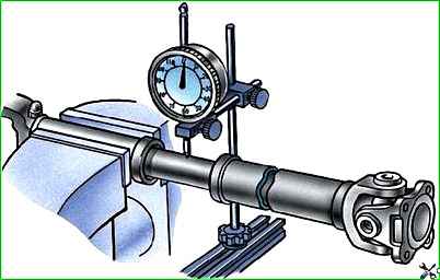
Measure the radial clearance of the driveshaft splines with an indicator (Fig. 2) at a distance of 75–80 mm from the splined end of the fork in two perpendicular planes and write down its value.
Disconnect the spline joint of the shaft, remove rings 9 (see Fig. 1), 10, 11 and race 12.
Remove retaining rings 2 using a screwdriver.
Using tool 71–2427, press out the needle bearing cups from the fork ear holes and disconnect the cardan forks.
Clean and rinse all parts of the driveshaft.
Assessment of the technical condition of driveshaft parts
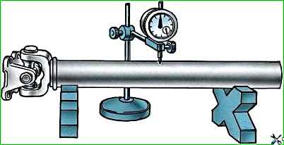
- 1. Straighten or replace the bent shaft. After straightening, the permissible shaft runout should be no more than 0.6 mm at any point along its length (Fig. 3). Straighten the shaft using prisms.
- 2. Replace the crosspiece if:
- – stud diameter less than 16.26 mm;
- – there are longitudinal dents on the spikes;
- – the necks of the cross under the cuff are very worn.
- 3. Replace the seal seals if their working edges are worn or damaged.
- 4. Replace needle bearings if:
- – bearings swing on spikes;
- – one of the needles is lost or deformed.
- 5. Replace worn parts of the propeller shaft stud connection if the radial clearance in the splines exceeds 1.3–1.5 mm.
- 6. Replace worn forks if the diameter of the bearing hole is more than 30.02 mm or the size between the planes of the fork ears exceeds 60.1 mm.
- 7. Replace the rubber or felt ring if it is worn or damaged.
- 8. Replace the spline seal race if the internal threads of the race are stripped.
- 9. If individual parts of the shaft are worn out or broken, replace the shaft if it is not possible to balance it.
It is possible to replace the crosspiece set with bearings and oil seals ics assembled without shaft balancing, if vibration does not occur.
Assembling the cardan shaft
- 1. Install cage 12 (see Fig. 1), felt ring 10, rubber ring 11 and rings 9 onto the splined end of the propeller shaft.
Before assembling the spline joint, impregnate felt ring 10 with lubricant and lubricate the splines.
- 2. Assemble the spline joint so that the universal joint forks are in the same plane; deviation no more than 5°.
To do this, align the marks (arrows) made before disassembly.
- 3. Screw the holder 12 all the way in and tighten it in two opposite places so that the edge of the holder is slightly bent into the recess of the sliding fork.
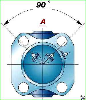
- 4. Install the crosspieces and hinge forks so that the grease fittings of the spline joint and the crosspiece located at the bridge are in the same plane and on the same side of the shaft, and the grease nipple of the crosspiece of the opposite end of the shaft is 90° counterclockwise when viewed from the bridge side ( Fig. 4).
- 5. Attach the fork with the cross into a fixture or vice and press the needle bearing cups into the eyes. At the same time, make sure that the working edge of the seals of the end seals of the bearings is not wrapped.
Install retaining rings 2 into the grooves of the glasses.
- 6. Assemble the universal joint of the opposite end of the shaft using the above method.
- 7. Before assembling, lubricate the hinges with Litol-24 grease; to do this, fill each bearing with grease to 1/2 of its volume.
- 8. After assembly, check:
- – ease of movement of the hinge forks.
The forks should move (without jamming) by hand;
- – the amount of angular movement in the hinges of the assembled cardan shaft.
The amount of angular movement for one joint should not exceed 0.3 mm (nominal value 0.23 mm) at a radius of 35 mm under the influence of a torque of 98-117 Nm (10-12 kgf m).
When replacing flanges or forks, balance the assembled shaft dynamically. The permissible imbalance after repair is no more than 26 gf cm.
Failures of cardan shafts
Cause of malfunction
- Elimination method
Vibration of the driveshaft (manifests itself in the form of a hum and intermittent noise, increasing with increasing vehicle speed)
Shaft balancing is out of balance - Balance the shaft. If this is not possible, then replace the shaft assembly with the hinge
Propeller shaft bent - Straighten or replace shaft
Excessive wear of the crosspiece trunnions. Longitudinal dents on the axles - Replace the crosspiece complete with bearings
Excessive wear on crosspiece needle bearings - Replace bearings
Excessive wear on the driveshaft spline - Replace the shaft
Wear of the holes in the ears of the forks and flanges of the driveshafts - Replace the shaft, flanges or sliding fork (if the holes in its ears are very worn)
Knocks or weak knocks in the cardan transmission that appear when changing gears or when the car moves by inertia
Loosening the bolts securing the propeller shaft to the flanges of the transfer case and drive axles - Tighten the bolts
Wear of the splines of the flanges securing the propeller shaft to the drive axles and transfer case - Replace the flanges
Excessive wear on the driveshaft spline - Replace the shaft
")

")
")
")
")
")
")
")