The technical condition of the engine is determined by fuel consumption, engine power, oil pressure, cylinder compression, engine noise and exhaust smoke
Measure the control fuel consumption on a car (after driving at least 9,000 km) moving in top gear with a full load on a dry, level asphalt or concrete road at a speed of 90 km/h.
The front axle must be disabled.
Carry out measurements on a section of road 3–5 km long in two opposite directions.
Before driving, warm up the engine and chassis components by driving the vehicle for 10–15 km.
To measure fuel consumption, you can use a tank model 361 GARO.
In winter, control fuel consumption can increase by no more than 10%.
The power qualities of the engine are determined by acceleration and the highest speed of the car.
The technical condition of the chassis unitsis determined by the free run-out distance of the vehicle.
On a flat section of asphalt highway, driving at a steady speed of 50 km/h, turn off the gear and let the car move quietly until it comes to a complete stop.
Measure the free run-out path when driving in two opposite directions.
Check the control fuel consumption and the “run-down” of the car when the engine is running normally, by external signs.
Before this, check and, if necessary, adjust the tire pressure, toe-in of the front wheels, and complete release of the brakes.
Tire tread wear should be no more than 50%.
The chassis is in good condition if the car (after a run of 9000 km) moves to a complete stop for at least 400 m.
Oil consumption during engine operation does not remain constant: during the running-in process it decreases and after a run of 5,000–7,000 km it becomes equal to 70–150 g per 100 km.
After a mileage of 70,000–90,000 km, oil consumption increases.
If oil consumption exceeds 450 g per 100 km, then the engine requires repair.
Measure oil consumption using the top-up method.
Check the oil pressure in the lubrication system with a control pressure gauge with a division value of no more than 49 kPa (0.5 kgf/cm 2), which is connected using a flexible hose instead of the oil pressure sensor.
To measure the oil pressure with a stationary car, raise the rear axle on stands, turn off the front axle, start the engine and, having engaged direct gear, open the carburetor throttle valve using a manual drive so that the speedometer shows a speed of 45 km/h, and measure the pressure in the system.
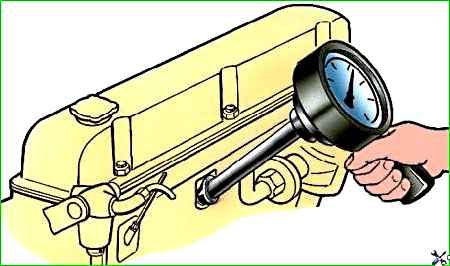
Check the compression in the cylinders on a warm engine with a compression gauge model 179 GARO.
To do this, unscrew the spark plugs, insert the rubber cone tip of the compression gauge into the hole for the spark plug (Fig. 1) and use the starter to turn the crankshaft with the throttle valve fully open and the carburetor without fuel.
The pressure in the cylinders must be at least 660 kPa (6.65 kgf/cm 3). The pressure difference in the cylinders should not exceed 98 kPa (1 kgf/cm 2).
Evenly reduced compression in all cylinders usually indicates significant wear of the cylinders and piston rings.
A decrease in compression in individual cylinders can occur as a result of “stuck” or burnt valves, burnt or broken piston rings, damaged cylinder head gasket, or improper clearance adjustment in the valve mechanism.
If, when pouring 25–30 cm 3 of clean oil into an engine cylinder with reduced compression, the pressure in it increases, this indicates a breakage of the piston rings or their coking in the piston grooves.
If compression does not increase, then the cause of the malfunction must be sought in leaks, stuck and burned valves, or damaged cylinder head gasket.
A decrease in compression in two adjacent cylinders indicates damage to the cylinder head gasket.
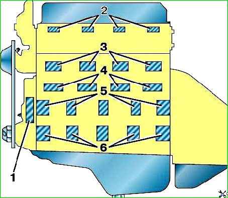
Listen to knocks and engine noises using a stethoscope model K-69M GARO on a warm engine at different crankshaft speeds (Fig. 2).
Start listening with the distribution mechanism at low and medium crankshaft speeds: valves at 550–1000 min -1, pushers at 1000–1500 min -1, distribution gears at 1000–2000 min -1.
Valve knocks can be clearly heard from the side of the head, above the valve locations;
- - knocking of the camshaft pushers and journals - from the side of the distribution mechanism, at the level of the camshaft axis;
- - knocking of timing gears - from the side of the cover.
Listen to the crank mechanism (pistons and main bearings) when there is a sharp change in engine crankshaft speed within 500–2500 min -1.
To determine the cylinder in which there is knocking from the crank mechanism, remove the wires from the spark plugs one by one.
Bearing knocks can be heard most clearly on the crankcase walls on the right side at the level of the camshaft:
- - knocking sounds of pistons and piston pins - on the walls of the cooling jacket against the corresponding cylinders.
- - The knocks of the main bearings are dull, and the knocks of the connecting rod bearings and piston pins are sharper and louder.
- - The knocking of the pistons is sharp, rattling. They can be heard in all engine operating modes.
Knocks of pistons, piston pins, main and connecting rod bearings, valves and pushers on a warm engine indicate engine malfunction.
Increased knocking of valves and tappets, merging into general engine noise when the crankshaft speed increases, or periodic knocking of valves, appearing and disappearing with a sharp change in crankshaft speed, as well as slight knocking of the pistons on a cold engine are not signs of engine malfunction .
We can also accept a slight high-pitched noise from the operation of the timing gears and oil pump gears.
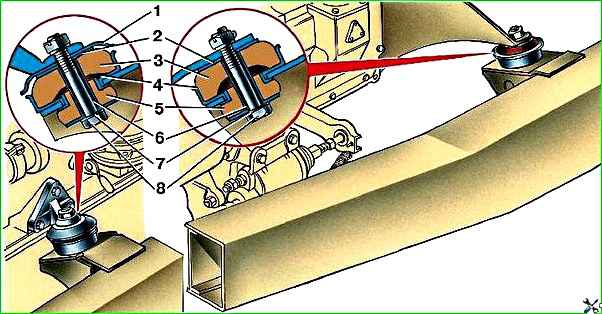
The engine is mounted on the frame at four points (Fig. 3).
Periodically check the tightness of the front and rear engine mount nuts.
")

")
")
")
")
")
")
")