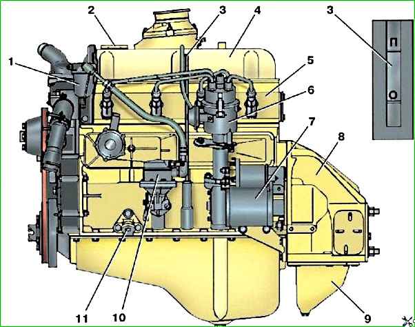
UAZ vehicles are equipped with a four-cylinder, four-stroke, overhead valve, carburetor engine with liquid cooling
Depending on the year of manufacture and configuration, engines of models 414, 4178, 4218 manufactured by JSC Volzhskie Motors (Ulyanovsk) and model 4021.60 manufactured by JSC Zavolzhsky Motor Plant (Zavolzhye, Nizhny Novgorod region) can be installed.
Model 4021.60 engines are designed for installation in UAZ vehicles.
The engine is a carburetor, four-cylinder, in-line, four-stroke, with two valves per cylinder. Cylinder operating order: 1-2-4-3.
The cylinder block is cast from aluminum alloy. The cylinder liners are cast iron cast into the block.
The aluminum clutch housing is bolted to the rear end of the block.
The pistons are cast from aluminum alloy. Each of them is equipped with two compression rings and one oil scraper ring.
Compression rings are cast iron, the top is chrome-plated, the bottom is tin-plated.
The piston pins are of the floating type; they are held against axial movement by retaining spring rings.
Connecting rods are steel, forged, I-section with a split lower head, the cover of which is secured with two bolts and nuts.
A bronze bushing is pressed into the upper (piston head) of the connecting rod.
The crankshaft is cast iron, cast, full-support, with counterweights, dynamically balanced in assembly with the flywheel and installed in the cylinder block on five detachable main plain bearings.
Main and connecting rod bearings are made in the form of liners made of steel tape coated with an antifriction aluminum-tin alloy.
The shaft is held against axial displacement by two thrust rings, which are installed on both sides of the front main bearing.
The ends of the crankshaft are sealed with rubber seals.
A hub is pressed onto the front toe of the crankshaft, to which the damper pulley is bolted.
The cylinder head is cast from aluminum alloy. Cast iron seats and cermet valve bushings are pressed into it.
The head is attached to the block with ten studs and nuts through a metal-asbestos gasket.
On the right side, the exhaust manifold and intake manifold are attached to the head.
The camshaft is cast iron, installed in bored holes in the lower part of the cylinder block.
At its front end, on a key, a textolite or polyamide helical drive gear is installed.
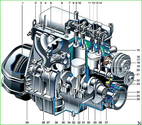
Engine: 1 - flywheel; 2 - mounting eye; 3 - heater tap; 4 - cylinder head cover; 5 - inlet pipeline; 6 - nuts of the studs securing the cylinder head; 7- valve rocker arm; 8 - rocker axis; 9 - crankcase ventilation pipe; 10 - cylinder head; 11 - valve springs; 12 - oil deflector cap; 13 - valve sleeve; 14 - oil filler cap; 15 - valve; 16 - cylinder head gasket; 17 - coolant pump; 18 - rod; 19 - pusher; 20 - fan pulley; 21 - camshaft; 2 - driven gear of the camshaft drive; 23 - torsional vibration damper; 24 - pulley hub; 25 - pulley; 26 - pulley bolt; 27 - cuff; 28 - camshaft drive gear; 29 - crankshaft; 30 - oil pan; 31 - cylinder liner; 32 - piston; 33 - oil drain plug; 34 - connecting rod; 35 - oil intake; 36 - oil pump; 37 - cylinder block; 38 - exhaust manifold; 39 - crankcase
The camshaft cams, when rotating, act on the cylindrical lamps that are installed in the holes of the block.
Aluminum push rods with steel spherical tips actuate valve rocker arms mounted on a common fixed steel axis.
On the short arm of the rocker there is a screw with a lock nut for adjusting the clearance in the valve drive.
Thin-walled bronze bushings are pressed into the rocker arm holes.
The valves are made of heat-resistant steel.
Each valve is equipped with two springs with right and left winding and is installed in a cermet guide bushing made of sintered copper-iron-graphite powder with molybdenum disulfide.
The valve stems are sealed with rubber oil deflector caps, which prevent oil from penetrating into the combustion chambers.
The top of the block head is closed with a stamped steel cover.
Combined lubrication system - under pressure and splashing.
The main and connecting rod bearings of the crankshaft, camshaft bearings, rocker arm bushings, and the upper tips of the pusher rods are lubricated under pressure.
The camshaft drive gears and the drive of auxiliary units are lubricated by a stream of oil, and the remaining parts are lubricated by splashing.
The cylinder walls are additionally lubricated by a stream of oil, which is ejected from the hole in the lower connecting rod head.
The gear oil pump is driven together with the ignition sensor-distributor by a screw drive from the camshaft.
The pump body is aluminum, and its working spur gears are made of cermet.
The oil is taken by the pump from the stamped steel oil pan through a mesh oil intake, then it passes through the pump, a full-flow filter and is supplied to the oil line.
The oil pressure in the system is limited by a pressure reducing valve.
")

")
")
")
")
")
")
")