Fill the hydraulic drive only with special brake fluid according to the instructions in the lubrication table in the following order:
- 1. Check the tightness of all hydraulic drive connections and the condition of flexible hoses.
- 2. Lift the hood (remove the radiator trim on a car of the UAZ-3741 family) and unscrew the caps of the master cylinder tanks. Fill the reservoirs with brake fluid.

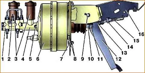
1 - signaling device; 2 - switch for the warning lamp of the emergency condition of the hydraulic brake system; 3 - tanks; 4 - main brake cylinder body; 5, 8 - nuts; 6 - vacuum booster; 7 - plate; 9 - pedal axis; 10 - fork; 11 - finger; 12 - pedal; 13 - stop; 14 - brake signal switch; 15 - tension spring; 16 - bracket
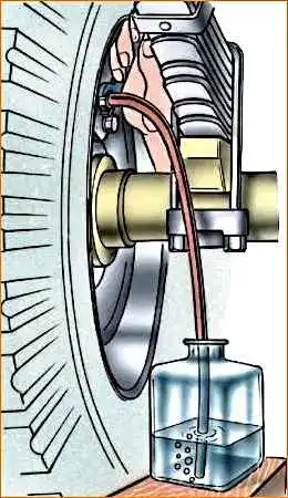
3. Remove the rubber cap from the bypass valve of the brake cylinder of the right rear brake mechanism and place a rubber hose about 400 mm long on the valve.
Dip the other end of the hose into a glass vessel with a capacity of at least 0.5 liters filled with brake fluid (Fig. 2).

4. Unscrew the bypass valve ½ - ¾ turn, then press the pedal several times.
Press the pedal quickly, release slowly.
Fluid under pressure from the piston of the main brake cylinder will fill the hydraulic drive and displace air.
Perform bleeding until the release of air bubbles from the hose lowered into the vessel with brake fluid stops.
During bleeding, add brake fluid to the master cylinder reservoirs, making sure not to expose their bottom so that air does not enter the system again.
Keep the end of the hose immersed in liquid throughout the filling operation.

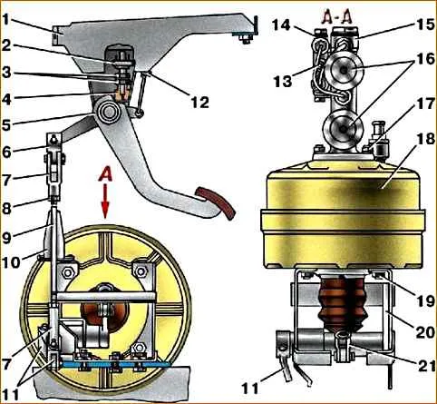
1, 20 - brackets; 2 - brake signal switch; 3 - nuts; 4 - buffer stop; 5 - pedal; 6 - intermediate fork; 7 - fork; 8 - lock nut; 9 - traction; 10 - cover; 11 - intermediate lever; 12 - tension spring; 13 - brake system emergency warning lamp switch; 14 - signaling device; 15 - main brake cylinder body; 16 - tanks; 17, 19 - nuts; 18 - vacuum booster; 21 - pusher fork
5. Tightly tighten the wheel cylinder bypass valve while pressing the pedal, remove the hose and put on the cap.
Bleed the hydraulic drive not only when it is filled with liquid, but also in the event of depressurization of the hydraulic drive of the rear brake working cylinder
6. Bleed the rear left brake cylinder, then the pressure regulator and the front brake cylinders.
On the brake mechanisms of the front wheels, first the lower and then the upper cylinder are pumped.
7. Turn off the alarm device by doing the following:
- – unscrew the bypass valve of the right or left working cylinder of the rear brake mechanisms;
- – gently press the pedal until the warning light on the instrument panel goes off; if the warning light flashes, this will mean that the indicator pistons have passed the neutral position, and therefore the operation must be repeated from the beginning, but only by unscrewing the front wheel bypass valve;
- – close the valve while pressing the pedal.
After bleeding all brake mechanisms, add fluid to the master cylinder reservoirs to a level 15–20 mm below the upper edges of the filler holes.
Tighten the lids tightly.
Do not add fluid to the brake master cylinder that is collected in a glass container during bleeding. If the brake fluid in the system is dirty, drain it and refill the system with fresh fluid.
Do not press the pedal with the brake drum removed, since under the pressure in the hydraulic drive the pistons will be squeezed out of the wheel cylinders and the fluid will flow out.
After filling the system with fluid, check the car for braking.
With proper adjustment of the working brake mechanisms and correct bleeding of the hydraulic drive, full braking should occur within ½ - 2/3 of the pedal stroke, after which the foot should feel a “hard” pedal.


