Maintenance and adjustment of the UAZ-3151 clutch
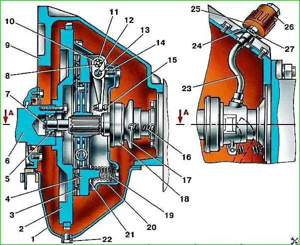
The clutch (Fig. 1) of the car is dry, single-disc, with hydraulic release.
Maintenance
The necessary work is carried out when disassembling the clutch.
Lubricate the clutch release bearing through the oiler cap located on the right side of the clutch housing, according to the lubrication table.
Access to the oiler from below the car.
Periodically drain the condensate from the clutch housing by removing plug 22 (Fig. 1).
Adjusting the clutch mechanism
Adjust the clutch mechanism with the clutch pressure plate removed in the following order.
Install the pressure plate assembly on the plate (a flywheel can be used instead of the plate) and secure it to the casing with six bolts.
Before fastening, install a replacement template for the driven disk in the form of a ring 9.5 mm thick between the plate and the pressure disk.
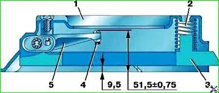
Adjustment is carried out by screwing in or unscrewing the adjusting screws (Fig. 2) until the size is (51.5±0.75) mm (the distance of the head of one of the screws from the surface of the plate).
The difference in the distance from the plate to the heads of the other two screws should not exceed 0.2 mm.
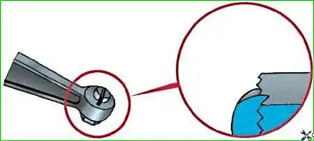
After adjustment, lock the screws of the 4 levers by pressing the edge of the lever into the groove of the screw, as shown in Fig. 3.
")

")
")
")
")
")
")
")