Repair of the crankshaft consists of regrinding the main and connecting rod journals to the next repair size
The repair dimensions of the connecting rod and main journals are determined by the dimensions of the sets of connecting rod and main bearings supplied as spare parts, which are given in table. 2. Tolerances of the main parts of the UAZ-3151 engine
Radial clearances in the connecting rod and main bearings of the crankshaft should be 0.020–0.049 mm and 0.020–0.066 mm, respectively.
Regrind the journals with a tolerance of 0.013 mm.
If the dimensions of the connecting rod and main journals do not match each other, they must be ground to one repair size.
The chamfers and holes at the front and rear ends of the crankshaft are not suitable for installation in a grinding machine. To do this, make removable glass centers.
Press the front center onto a neck with a diameter of 38 mm, and center the rear center along the outer diameter of the flange (Ø122 mm) of the shaft and bolt it to it.
When making transition centers, ensure that the center and mounting holes are concentric.
Without observing this condition, it is impossible to ensure the necessary concentricity of the flywheel and gear seats to the axes of the main journals.
When grinding the connecting rod journals, install the shaft on additional centers, coaxial to the axes of the connecting rod journals.
To do this, you can use glass centers, providing them with flanges with two additional center holes spaced from the middle hole by 46±0.05 mm.
For the front end, it is better to make a new center flange, which is installed on a neck with a diameter of 40 mm (on a key) and additionally secured with a bolt (ratchet) screwed into a threaded hole.
Before grinding the journals, deepen the chamfers on the edges of the oil channels so that their width after removing the entire grinding allowance is 0.8–1.2 mm.
Do this using an emery stone with an apex angle of 60–90° driven by an electric drill.
When grinding the connecting rod journals, do not touch the side surfaces of the journals with the grinding wheel so as not to disturb the axial clearance of the connecting rods.
Keep the radius of the transition to the side surface to 3.5 mm.
Grind with plenty of emulsion cooling.
During the grinding process, maintain:
- 1. The distance between the axes of the main and connecting rod journals is 46±0.05 mm.
- 2. Cone shape, barrel shape, saddle shape, oval shape and cut necks no more than 0.005 mm.
- 3. The angular position of the connecting rod journals is ±0°10'.
- 4. The non-parallelism of the axes of the connecting rod journals with the axis of the main journals is no more than 0.012 mm over the entire length of the connecting rod journal.
- 5. Runout (when installing the shaft with the outer main journals on the prisms) of the middle main journals is no more than 0.02 mm, of the journal for the camshaft gear up to 0.03 mm, and for the journals for the pulley hub and rear oil seal up to 0.04 mm.
After grinding the journals, wash the crankshaft and clean the oil channels from abrasive and resinous deposits.
Unscrew the plugs of the dirt traps.
After cleaning the dirt traps and channels, screw the plugs back into place and secure each of them to prevent spontaneous unscrewing.
Clean the oil channels also during operational repairs of the engine, when the crankshaft is removed from the block.
After repair, reassemble the crankshaft with the same flywheel and clutch that were installed before repair.
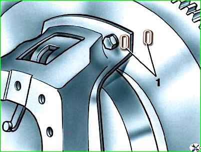
Install the clutch on the flywheel according to the factory “O” marks marked on both parts, one opposite the other, near one of the bolts securing the clutch housing to the flywheel (Fig. 1).
Before installing the crankshaft and clutch assembly on the engine, dynamically balance it on a special machine.
Pre-align the clutch driven disc using the gearbox shaft or a special mandrel.
Eliminate imbalance by drilling metal in the flywheel rim at a radius of 158 mm with a drill with a diameter of 12 mm.
Drilling depth should not exceed 12 mm. Permissible imbalance – no more than 70 gsm.
Replacing the main and connecting rod bearings of the crankshaft
Spare parts include main and connecting rod bearing shells of nominal and seven repair sizes, which are given in table. 2. Tolerances of the main parts of the UAZ-3151 engine
Repair size liners differ from nominal size liners by an internal diameter reduced by 0.05; 0.25; 0.50; 0.75; 1.0; 1.25 and 1.50 mm.
Replace the main and connecting rod bearing shells without any adjustment.
Depending on the wear of the journals, when changing the liners for the first time, use liners of the nominal or, in extreme cases, the first repair size (reduced by 0.05 mm).
Install bearings of the second and subsequent repair sizes into the engine only after grinding the crankshaft journals.
If, as a result of repeated grinding, the diameters of the crankshaft journals are reduced so much that the liners of the last repair size turn out to be unsuitable for it, then reassemble the engine with a new shaft.
The radial clearance in the connecting rod and main bearings of the crankshaft should be 0.020–0.049 mm and 0.020–0.066 mm, respectively.
Check the size of the radial clearances using a set of test probes made of copper foil with a thickness of 0.025; 0.05; 0.075 and 0.1 mm, cut into strips 6–7 mm wide and slightly less than the width of the liner.
The edges of the probes must be cleaned to prevent damage to the surface of the liner.
Check the radial clearance in the following order:
- 1. Remove the cover with the liner from the neck being tested and place a pre-oiled 0.025 mm thick test probe across the liner.
- 2. Replace the cover with the liner and tighten the bolts, while the bolts of the remaining covers must be loosened.
- 3. Rotate the crankshaft by hand at an angle of no more than 60–90° to avoid damaging the surface of the liner with the feeler gauge.
If the shaft turns too easily, then the gap is greater than 0.025 mm.
In this case, repeat the test with probes 0.05; 0.075 mm, etc. until it becomes impossible to turn the crankshaft.
The thickness of the feeler gauge, at which the shaft rotates with noticeable force, is considered equal to the actual value of the gap between the liner and the crankshaft journal.
When replacing earbuds, observe the following:
- 1. Replace the inserts without adjustment operations.
- 2. Make sure that the locking protrusions at the joints of the liners fit freely (by hand) into the grooves in the shaft beds.
- 3. At the same time as replacing the bearings, clean the dirt traps in the connecting rod journals.
The connecting rod bearings can be replaced without removing the engine from the vehicle chassis.
Replace the main bearings with the engine removed from the vehicle chassis.
After replacing the liners, run in the engine as indicated in “Running in the engine after repair.”
If the engine was not removed from the car when replacing the liners, then during the first 1000 km the speed should not exceed 50 km/h.
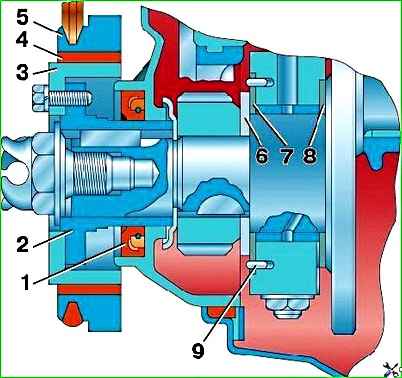
At the same time as replacing the liners, check the axial clearance in the crankshaft thrust bearing, which should be 0.075–0.175 mm.
If the axial clearance is more than 0.175 mm, replace washers 7 (Fig. 2) and 8 with new ones.
The front washer is made in four thickness sizes:
- 2,350–2,375;
- 2,375–2,400;
- 2,400–2,425;
- 2.425–2.450 mm.
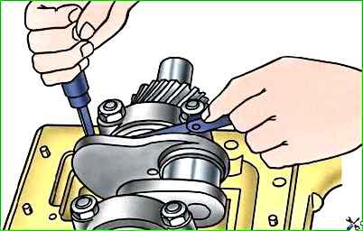
To check the clearance in the thrust bearing, place a screwdriver (Fig. 3) between the first crank of the shaft and the front wall of the block and press the shaft towards the rear end of the engine.
Then use a feeler gauge to determine the gap between the end of the rear washer of the thrust bearing and the plane of the shoulder of the first main journal.
Before installing the liners, check the alignment of the crankshaft main journals (deflection arrow).
To do this, install the crankshaft in the centers and check the position of the axes of the main journals according to the indicator readings.
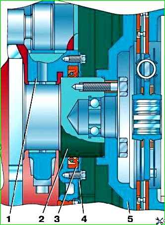
The front and rear ends of the crankshaft are sealed with oil seals (Fig. 2 and 4).