Disconnect the wire from the negative terminal of the battery.
Install the piston of the 1st cylinder in the idle position. compression stroke.
To do this, turn the crankshaft so that the third mark on the pulley aligns with the boss on the camshaft sprocket cover.
After this, remove the distributor cap and check that the slider is in the contact position of the 1st cylinder.
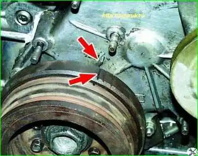
Otherwise, turn the crankshaft one turn
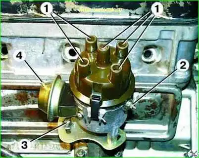
Disconnect the high-voltage wires by removing them from terminals 1 of the distributor cover, and disconnect the wire from the low-voltage terminal of the distributor by unscrewing nut 2.
Disconnect the vacuum hose from fitting 4 of the vacuum corrector.
Unscrew bolt 3 and lift out the ignition distributor upwards.
Disassembling the ignition distributor
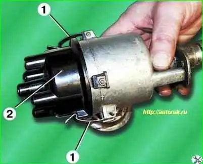
Unfasten the spring clips 1 and remove the distributor cover 2.
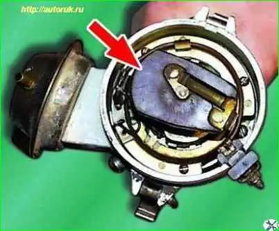
Remove the slider by pulling it up.
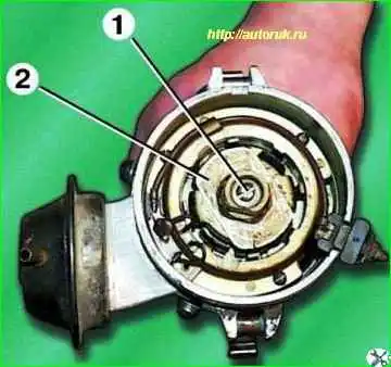
Take out the felt pad and unscrew the screw 1 underneath it.
Remove rotor 2.
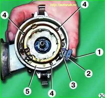
Unscrew nuts 1 and disconnect wire 3 from terminal 2.
Pull up terminal 2.
Unscrew three screws 4 and remove stator 5
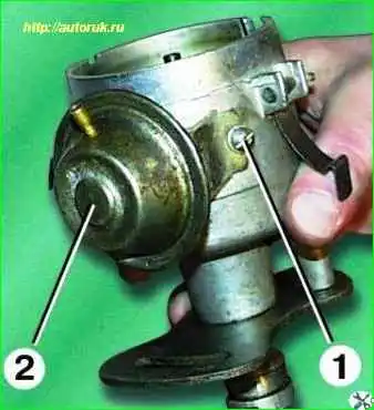
Unscrew the two screws 1 and remove the vacuum corrector 2.
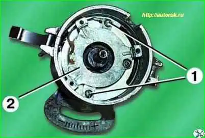
Unscrew the two screws 1 and remove the stator support 2 with the bearing assembly.
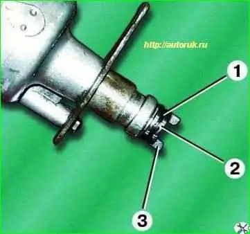
Remove the spring ring 1, pick it up with a screwdriver, remove the pin 2 and remove the distributor drive clutch 3.
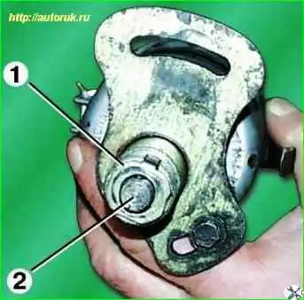
Remove lock washer 1 and remove distributor shaft 2 with central regulator
Unscrew the fastening bolt 1 and remove the octane corrector plate 2.
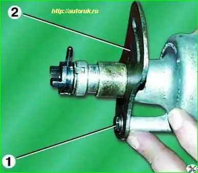
Assemble the ignition distributor in the reverse order of disassembly. In this case, it is necessary to lubricate the roller, bushings and bearing with CIATIM-221 lubricant.
Inspection and troubleshooting of ignition distributor parts
Wipe the inside and outside of the distributor cap.
Inspect the cover. If there are cracks, chips, or badly worn contacts 1 inside the cover, the cover must be replaced.
Contact angle 2 must move freely in the cover.
The runner must be tightly installed on the rotor, otherwise replace it.
A leaf spring must be installed on the bottom of the runner.
If the runner has cracks, burn marks, significant wear, or corrosion of the runner current carrying plate, replace it.
Check the rotation of the bearing in the stator support. If there is binding, ball rolling, or significant play is noticeable in the bearing, replace the stator support.
If wire 1 is broken, also replace the stator support.
Inspect the stator.
On the inner surface of the stator there should be no traces of the rotor touching it. If wire 1 is broken, replace the stator.
Check the resistance of the stator winding with an ohmmeter; it should be in the range of 264-396 Ohms. If the resistance is different from the specified value, replace the stator.
Inspect the rotor. If there are traces of contact with the stator, check the radial clearance of the rotor on the distributor shaft using an indicator.
The maximum permissible gap is 0.2 mm. If the gap is larger, replace the rotor or rotor with shaft.
Inspect the distributor drive coupling. If excessive wear is visible on the protruding ends of the coupling, replace the coupling.
Weights 1 of the centrifugal regulator must rotate freely on the axes, otherwise eliminate the cause of the weights jamming.
The centrifugal regulator is adjusted by bending the struts of 2 springs.
If there are burrs on the roller or signs of significant wear, replace the roller.
Measure the diameters of the roller under the rotor and under the bushings, they should be equal to 8.5 ≤0.015 and 85≤0.035 mm and 12.7 ≤0.2 mm, respectively.
The runout between the ends of the roller should not exceed 0.01 mm. If at least one size does not fit within the specified limits, replace the roller.
Inspect the bushings in which the roller rotates on both sides of the distributor housing.
If scuffing or significant wear is detected, replace the bushings.
The maximum permissible axial clearance of the distributor shaft in the bushings is 0.2 mm; if the bushing has a larger gap, replace the bushings.
To do this, press out the old bushings, then press in new ones and expand them to a diameter of 12.7 +0.012 and 12.7 ≤0.060 mm.
Installing the ignition distributor
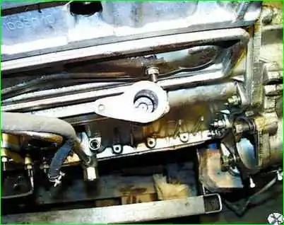
Check that the grooves of the ignition distributor and oil pump drive shaft are installed parallel to the engine axis and offset from the shaft axis away from the engine.
Remove the distributor cap, insert the distributor into the drive housing.
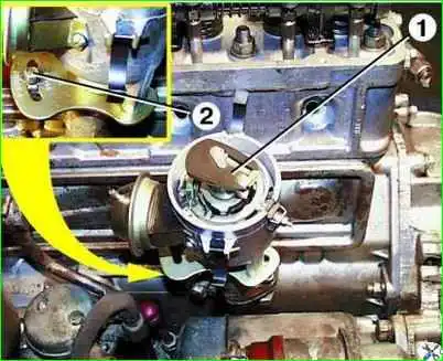
Turning slider 1, align the protrusions of the distributor drive coupling with the grooves of the drive shaft so that the distributor snaps into place.
In this case, the slider should be in the contact position of the 1st cylinder.
Tighten bolt 2 securing the distributor.
After installing the distributor, adjust the ignition timing.


