Disassemble the bridge in the following order:
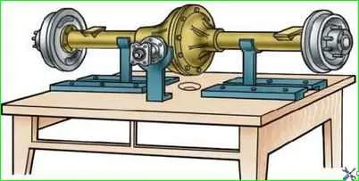
Install the bridge on the stand (Fig. 1), unscrew the oil filler and oil drain plugs and drain the oil.
Unscrew the bolts securing the axle shafts and, using them, remove the axle shafts.
Unscrew the nuts and bolts securing the cover and crankcase, carefully separate the bridge into two parts. Remove the gasket.
Remove the differential and driven gear assembly from the housing.
Remove the main drive gear.
Without disassembling the axle, it is impossible to remove the drive gear, since when the gear with bearings assembly is pressed out of the axle housing, the rear bearing (with cylindrical rollers) will rest against the driven gear.
To remove the drive gear, unscrew and unscrew the nut on the shank, remove the washer and flange, unscrew the bolts and remove the drive gear front bearing cover.
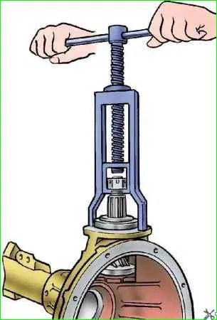
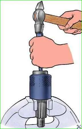
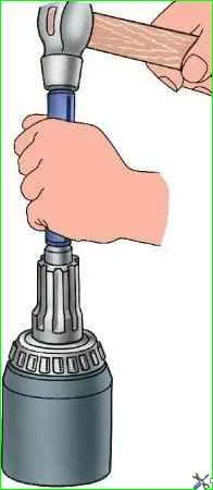
Remove the oil removal ring and use a tool to press the drive gear (Fig. 2) with the bearing assembly out of the crankcase.
Disassemble the differential in the following order:
- – unscrew the bolts securing the driven gear to the satellite box; remove the driven gear;
- – unscrew the bolts securing the halves of the satellite box;
- – disconnect the right half of the gearbox from the left and remove the differential gears, satellite axles and support washers.
Assessment of the technical condition of parts
After disassembling the bridge, thoroughly rinse the parts in kerosene and inspect them.
Replace gears with scoring and chipping on the teeth.
Replace bearings that are worn. If the bearings and associated parts do not require replacement, then do not press out the bearing rings.
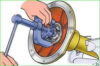
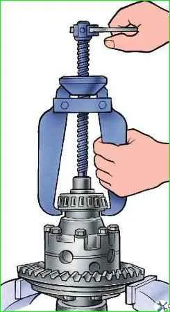
Press out the outer rings of the bearings (Fig. 3) of the differential from the crankcase and cover and remove the inner rings (Fig. 4) of these bearings using tools.
Removal of the rear and front drive gear bearings is shown in Fig. 5 and 6.
The end of the neck on which the rear bearing is pressed is open, therefore, press it out only for replacement.
When disassembling the bridge, do not disassemble the inner and outer rings of the differential and drive gear bearings, and when reassembling, install the bearings that do not need to be replaced in their original places.
The oil removal ring must have smooth ends.
If necessary, sand it to a thickness of at least 5 mm.
Cardan flange
The end of the flange associated with the oil removal ring must be smooth. If necessary, sand it to a height of at least 53 mm.
Axle housing
Remove all irregularities and burrs from the seating and adjacent surfaces of the crankcase.
Clean the oil channels.
Differentials and axle shafts
Thrust washers, pinion axles, pinions, axle gears and pinion boxes with scoring and heavy wear.
Replace satellites and semi-axial gears as a complete set.
Replace the side gear thrust washer if its thickness is less than 1.2 mm.
If the ends of the satellite box are worn, it is allowed to install washers increased in thickness by 0.1 mm or 0.2 mm.