Constantly monitor the serviceability of the working brake system, adjust it in a timely manner and eliminate any malfunctions
Systematically check the fluid level in the master cylinder reservoirs and, if necessary, bring it up to normal.
The level should be 15–20 mm below the upper edges of the filling holes.
Make sure the connections of the hydraulic drive pipelines are tight.
Check the condition of the pipelines, the reliability of the pipes on the frame and rear axle.
During inspections, make sure that there is no damage to tubes and flexible hoses.
Replace damaged pipes and hoses with new ones.
During seasonal maintenance, check the operation of the pressure regulator.
Clean the regulator from dirt and check the reliability of its fastening.
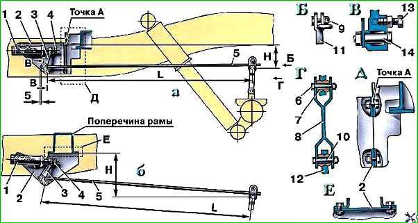
By external inspection, make sure that the regulator and its drive parts are not damaged, there are no brake fluid leaks and there are no gaps in the connection of the strut with the elastic lever and the bracket on the rear axle (Fig. 2).
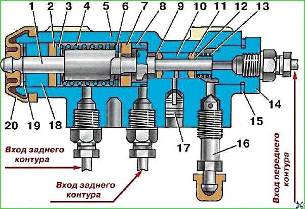
When you press the brake pedal, piston 1 (see Fig. 1) of the pressure regulator should move out of the housing by 1.7–2.3 mm.
Lack of piston stroke, as well as insufficient or excessive stroke, indicates a malfunction of the regulator or its drive.
When inspecting the hydraulic drive, pay attention to the location of the plastic (control) plug 17 and the absence of brake fluid leaking from under it.
In normal condition, the plug should be recessed into the hole in the regulator body until it stops.
The protrusion of the plug from the hole and the leakage of brake fluid mean a loss of tightness of the sealing rings 11 and, as a consequence, the functionality of the regulator.
As necessary, check the reliability of the vacuum booster, wash or replace the booster air filter.
Periodically remove the brake drums and clean the brake parts from dirt.
In the summer and when driving on dirty roads, clean more often.
When removing the brake drum, make sure that there are no leaks from the wheel brake cylinders, as well as that the wheel cylinders are securely attached to the shields.
Pay attention to the condition of the wheel cylinder protective caps, the degree of wear of the friction linings, and the condition of the brake drum.
If the surfaces of the linings become oily, clean them with sandpaper.
With the hubs removed, tighten the bolts securing the brake shields.
Wash the hydraulic drive regularly and fill it with fresh brake fluid.
To thoroughly flush the hydraulic drive, disassemble the main and wheel brake cylinders, the pressure regulator, and blow out the pipelines with compressed air.
When disassembling cylinders, maintain cleanliness.
Wash rubber and metal parts of the cylinders in clean brake fluid.
Do not use kerosene or gasoline, as this will cause swelling of the rubber parts and failure of the brake system.
During assembly, it is recommended to lubricate the working parts of the cylinders with brake fluid.
")

")
")
")
")
")
")
")