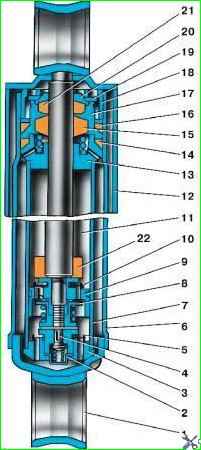
Periodically check the condition of springs, suspension springs and shock absorbers, their fastening and eliminate any identified faults
The spring leaves must not have cracks.
Cutting the center bolt of the spring can cause longitudinal displacement of the sheets, and loosening the tightening of the stepladders can cause transverse displacement of the sheets.
To prevent corrosion and eliminate squeaking, lubricate the spring leaves according to the instructions in the lubrication table.
Knocks and creaks in the spring ears and spring suspension hinges indicate wear or incomplete tightening of the rubber bushings or wear of the rubber-to-metal hinges.
In this case, replace the joints and bushings or tighten the bushings more tightly.
To increase the tension in the spring bushings, install rubber gaskets (rings) cut from a tube or similar rubber between them.
A sign of a faulty shock absorber is prolonged rocking of the car after driving over an uneven road.
When servicing shock absorbers, periodically inspect and promptly tighten their fastenings, and also check the condition of the rubber bushings in the ears.
The shock absorber does not require special adjustments during operation.
Disassemble shock absorbers only in the following cases:
- – the occurrence of an unrepairable liquid leak;
- – loss of shock absorber forces during tension or compression;
- – fluid replacement.

The shock absorber should not be disassembled unless absolutely necessary.
Before disassembling the shock absorber, clean it of dirt, rinse and wipe thoroughly.
Carry out disassembly and subsequent assembly operations in conditions that ensure complete cleanliness.
After the first 3000 km or if fluid leaks through the oil seal 15 (see Fig. 1) of the rod and sealing rings 14,16, tighten nut 18. Tightening torque 78–98 Nm (8–10 kgf m).
If the leakage does not stop, remove the shock absorber, disassemble it, inspect the O-rings and the hole in the rod guide sleeve 13.
Replace the rod seal, rod guide, reservoir sealing rings and other parts worn along the inner diameter.
Install the rubber oil seal 15 with the inscription “bottom” on it towards the piston.
When installing the oil seal, lubricate its internal surfaces mating with the rod with shock-absorbing fluid to reduce wear and prevent squeaking.
Reduced shock absorber efficiency or failure can be caused by clogged valve systems, settling of valve springs, or broken parts.
In such cases, disassemble the shock absorber, wash it and replace sagging or broken springs and parts.


