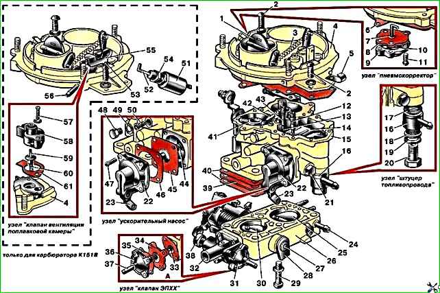
Carburetor K-151V (Fig. 1) - vertical, emulsion, two-chamber, with a falling mixture flow and sequential opening of the throttle valves
The carburetor has:
- - balanced float chamber, two main dosing systems - the first and second chambers,
- - autonomous idle system in the primary chamber with quantitative regulation of the mixture of constant composition with a forced idle economizer (EFCH),
- - transition systems of the primary and secondary chambers,
- - econostat with output to the secondary chamber,
- - diaphragm accelerator pump with a mechanical drive from the throttle valve shaft of the primary chamber and with a nozzle outlet into the primary chamber,
- - semi-automatic system for starting and warming up the engine with manual control.
In addition, the carburetor is equipped with a float chamber ventilation valve.
Maintenance of the carburetor consists of periodically checking the reliability of fastening of the carburetor and its individual elements, checking and adjusting the fuel level in the float chamber, adjusting the low speed of the engine crankshaft, cleaning, purging and flushing carburetor parts from tarry deposits, checking the throughput of the jets.
Check the fuel level with the car engine not running, installed on a horizontal platform and the carburetor cover removed.
The float chamber is filled with fuel using the manual pump lever.
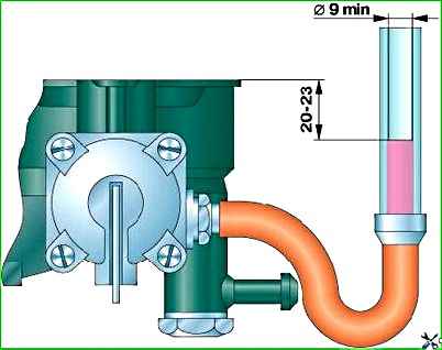
The fuel level (Fig. 2) should be within 20–23 mm from the plane of the float chamber connector.
To check it, you need to screw in a fitting with an M 10xl–6g thread to connect the rubber hose.
The fitting is screwed into the float chamber instead of the drain plug. The fuel level is determined through a transparent tube with an internal diameter of at least 9 mm.
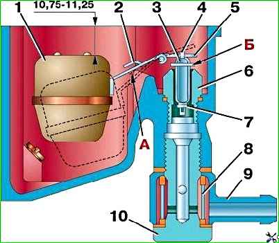
The level is adjusted by bending tongue 5 of the float loop (Fig. 3) to a size of 10.75–11.25 mm between the top of the float and the plane of the float chamber connector (the float must be raised to its highest position).
In the lowest position, the float should not touch the walls of the float chamber, and its tongue 2 should be on the stop “A”. In this case, the stroke of valve 3 should be equal to 1.5+0.5 mm.
The valve stroke is adjusted by bending the tongue 2 of the float loop.
After adjustment, check the fuel level again and, if necessary, reset adjustment again. If the adjustment does not give the desired result, it is necessary to check the float mechanism.
Usually the reasons for an increased or decreased fuel level in the float chamber are the asymmetry of the float, incorrect weight, and a stuck or leaking fuel valve.
The tightness of the float is checked by immersing it in water heated to 80–85°C for at least 30 seconds.
The mass of the float assembly with the loop after repair should not be more than 13 g. If the fuel valve is leaking, sealing washer 7 should be replaced.
After replacing the sealing washer, when assembling valve 3 with shackle 4, it is necessary to take into account that the shackle must be installed in such a way that the protrusion of shackle “B” is directed in the direction opposite to the float.
Adjustment of the minimum crankshaft speed 550–650 min -1(700–750 min -1 – for engines model 4218) in idle mode must be carried out on a warm engine (coolant temperature 70°C) with a working ignition system.
During vehicle operation, the minimum idle speed is adjusted by turning the operational adjustment screw.
When unscrewing a screw, the rotation speed increases, when screwing it in, it decreases.
If it is not possible to achieve stable engine operation by rotating the operational adjustment screw, you should turn out the mixture screw until it stops on the limiting bushing (pressed onto the screw) and again adjust the minimum frequency using the operational adjustment screw.
Full carburetor adjustment is carried out at a service station (using gas analysis equipment) and must be carried out under the following conditions:
- – on a warm engine;
- – with adjusted gaps in the gas distribution mechanism;
- – with serviceable spark plugs and adjusted ignition timing;
- – with the air damper fully open.
Adjustment sequence:
- 1. Adjust the operational adjustment screw to the minimum idle speed.
- 2. Adjust the mixture composition screw to control the carbon monoxide (CO) content within 1.0–1.5%, having previously removed the restrictive sleeve.
The content of hydrocarbons (CH) should not exceed 1000 min –1.
- 3. Make sure that the selected position of the screws ensures normal operation of the engine during throttle changes; to do this, open the throttle slightly and release it sharply.
If at the same time engine stops or unstable operation are noted, then it is necessary either to increase the minimum speed by unscrewing the operational adjustment screw, or to enrich the mixture with the mixture screw.
The maximum permissible CO content is not more than 2%.
4. Increase rotation speed to 2400 min -1 . The CO content should be no more than 1%; CH – no more than 500 min –1.
After the final adjustment, install the limiting sleeve on the mixture adjustment screw and mark its position.
Warm the engine to a coolant temperature of 80–85°C and check the CO content in the exhaust gases at idle speed.
The CO content should not exceed 4.5% in any position of the toxicity screw, which allows the restrictor sleeve to be installed.
Install the screw with the limit sleeve in the marked position.
It is not allowed to adjust the minimum crankshaft speed using the throttle valve opening screws.
When checking the operation of the carburetor, pay attention to the operation of the float chamber ventilation valve (reliability of wire connections, absence of jamming and valve tightness).
A malfunction of the valve leads to increased fuel consumption and difficulty starting a hot engine.
Rinse carburetor parts with benzene or unleaded gasoline, then blow with compressed air.
Do not use metal wire to clean jets and calibrated holes, as this will disrupt their dimensions and capacity.
In order not to confuse the jets during installation, you should pay attention to their markings.
Each jet is marked with the nominal flow rate in ml/min.
The marking is applied by impact on the nozzle head (from the spline side).