Check the wheel bearings periodically and, if necessary, adjust them
Check the presence of clearance in the bearings by rocking the hanging wheel.
Pay special attention to the correct adjustment of the wheel hub bearings of a new car.
Periodically check and tighten the fastenings of the axle flanges and hub drive flanges.
Systematically change the lubricant in the wheel hubs in accordance with the lubrication table.
To replace the grease, remove the hub from the axle, remove the old grease and thoroughly rinse the bearings and the internal cavity of the hub with kerosene.
The layer of lubricant in the hub between the bearings should be 10–15 mm thick.
Do not put more grease into the hub to avoid getting it into the wheel brake mechanism.
When washing and replacing lubricant, do not remove the cuff to avoid damaging it and breaking the seal.
Press out the cuff only if the grease is heavily contaminated and the hub bearings are being replaced.
Periodically inspect the wheels and check the tightness of the wheel nuts. The tightening torque of the nuts is 98–118 Nm (10–12 kgf m).
For even tightening, tighten the nuts one at a time. To prevent the nuts from seizing, lubricate them every time you remove the wheel.
If a wheel is faulty, repair or replace it.
Use tires with a “universal” or all-season tread pattern.
When operating vehicles on unpaved roads, use tires with an all-terrain tread pattern.
Check the condition of your tires and their air pressure periodically, and rotate the tires and balance the wheel and tire assemblies as necessary.
Check the pressure on cold tires.
If necessary, bring it to normal.
Make sure that tire tread wear does not exceed the maximum value (up to wear indicators, and in their absence, up to 1.6 mm of the remaining tread depth).

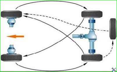
If the tread wear is uneven, rearrange the tires in the sequence shown in Fig. 1.
When rotating bias tires, use the spare tire if its wear does not differ from the other tires.
The rotation of radial tires should be on the side - the front and rear wheels on one side are swapped.
The spare wheel is not involved in the rearrangement scheme.
If the front tires wear intensively and unevenly, check and, if necessary, adjust the wheel toe-in, which should be 1.5–3 mm.
If “spotty” tire wear appears or increased feedback on the steering wheel, check and, if necessary, carry out static or dynamic balancing of the wheels and tires assemblies.
It is also recommended to carry out wheel balancing as a preventative measure simultaneously with tire rotation in order to prevent increased wear of tires and steering parts.
Preventive wheel balancing is especially necessary on vehicles of the UAZ-31512 family.
Balancing wheels and tires assemblies
Before balancing, the wheel must be cleaned of dirt.
To facilitate installation of the balancing weight spring, it is recommended to reduce the tire pressure to 50 kPa (0.5 kgf/cm 2).
The imbalance of the wheel and tire assembly should not be more than 1600 g cm (40 g at the edge of the rim on each side).
Dynamic wheel balancing is performed on a special machine.
If it is not possible to carry out full dynamic balancing, you can carry out static balancing on a device that simulates the rotation of a wheel on the hub, on which it is necessary to ensure the greatest ease of rotation.
The wheels are balanced using special weights and springs installed on the rim flange.
Balancing on the device is carried out as follows:
- 1. Set the wheel in rotation. After stopping the wheel, put a mark with chalk on its upper (light) part.
- 2. Repeat the operation, rotating the wheel in the opposite direction, and apply a second mark on the top.
- 3. Divide the distance between the marks in half and place a third (middle) mark, which will determine the easy spot of the wheel.
- 4. Place one or more weights near the third (middle) mark to completely balance the wheel.
If it is not possible to accurately select the mass of the weights, then instead of the initially installed weights on both sides of the mark, place an even number of identical weights in pairs, the total mass of which slightly exceeds the required one, and then, moving them apart at equal distances from the light point of the wheel, achieve an indifferent balance.
5. Separate the pores as much as possible well, select weights based on weight and place the wheels opposite each other on both sides.


