Repair and maintenance of the front axle UAZ-3151
The main gear and differential of the front axle are similar in design to the rear axle
All instructions for maintenance and repair of the rear axle also apply to the front axle
Additionally, the steering knuckles are serviced and repaired (Fig. 1).
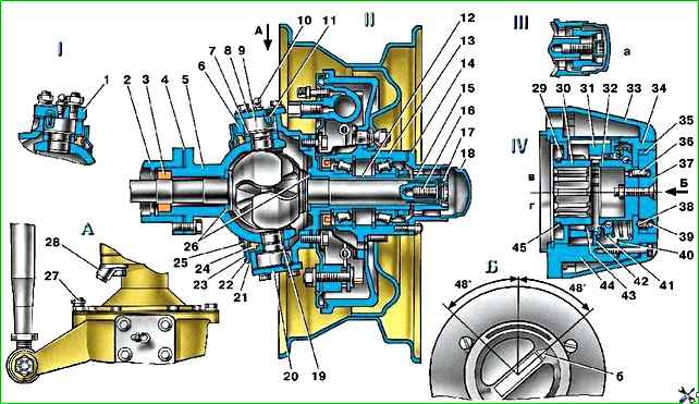
Fig. 1. Steering knuckle: a - signal groove; b - pointer; I - right steering knuckle; II - left steering knuckle; III - wheel release clutch; IV - wheel release clutch (optional); c - wheels are disabled; d - wheels are on; 1 - steering knuckle lever; 2 - axle housing; 3 - oil seal; 4, 20 - gaskets; 5 - ball joint; 6 - steering knuckle body; 7 - support washer; 8 - overlay; 9 - kingpin; 10 - grease fitting; 11 - locking pin; 12 - axle; 13 - wheel hub; 14 - leading flange; 15 - coupling: 16 - coupling bolt; 17 - locking ball; 18 - protective cap; 19 - pin bushing; 21 - inner race; 22 - partition ring; 23 - outer ring; 24 - rubber sealing ring; 25 - felt sealing ring; 26 - thrust washers; 27 - rotation limitation bolt; 28 - wheel rotation limiter; 29 - ring; 30 - drive spline bushing; 31 - connecting spline bushing; 32 - drive bushing; 33 - cap; 34 - cover: 35 - cuff; 36 - pin; 37 - switch; 38 - ball; 39.41 - springs; 40 - gasket; 42 - driven bushing; 43 - extension spring; 44 - body; 45 - locking ring
Maintenance
When servicing the front drive axle, check and, if necessary, adjust the tightening of the kingpin bearings, wheel toe-in and maximum wheel rotation angles, check and tighten the steering knuckle arm fastening, wash and change the lubricant in the steering knuckles.
When inspecting the steering knuckles, pay attention to the serviceability of the wheel rotation stops 28 (Fig. 1), adjusting bolts 27 and the reliability of their locking.
Check and adjust the axial clearance of the kingpins on the car in the following order:
Stop the car using the parking brake or chock the rear wheels.
Raise the front axle with a jack.
Unscrew the wheel nuts and remove it.
Unscrew the bolts securing the ball joint oil seal and move the oil seal aside.
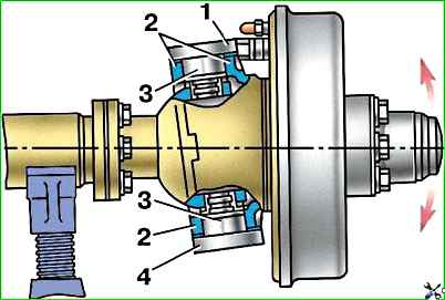
Check the axial clearance of the pins by shaking the steering knuckle body up and down with your hands (Fig. 2).
Unscrew the nuts of the studs securing the lever 1 (see Fig. 1) of the steering knuckle or the bolts securing the upper lining 1 (see Fig. 2) and remove the lever or the upper lining of the king pin.
Remove the thin (0.1 mm) shim and install the lever or trim in place.
Unscrew the fastening bolts and remove the lower pad 4 of the king pin, remove the thin (0.1 mm) adjusting shim and install the king pin pad in place.
To maintain joint alignment, remove shims of equal thickness from top and bottom.
Check the build results.
If the gap is not eliminated, readjust by removing thicker shims (0.15 mm).
Excessive wear of the pins 9 and bushings 19 (see Fig. 1) in diameter causes a violation of the camber angle of the wheels, their “wobbling” when driving and uneven wear of the tires. In this case, replace the worn parts.
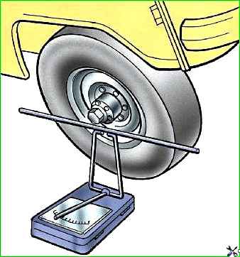
Check the maximum wheel rotation angles on a special stand (Fig. 3).
The angle of rotation of the right wheel to the right, and the left wheel to the left should be no more than 27°. Make adjustments using bolt 27 (see Fig. 1).
Wheel toe adjust by changing the length of the tie rod.
Before adjusting, make sure there are no gaps in the steering rod joints and hub bearings; then, loosening the lock nuts (having right-hand and left-hand threads), rotate the adjusting fitting to set the required wheel toe value.
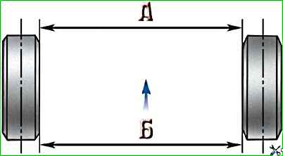
The toe-in of wheels at normal tire pressure should be such that size A (Fig. 4), measured along the center line of the side front tire surface was 1.5 –3.0 mm smaller than the B size at the rear. p>
When adjustment is complete, tighten the lock nuts. Tightening torque 103–127 Nm (10.5–13 kgf m).
Wheel alignment can be checked using the model 2182 GARO ruler.
Repair
To carry out repairs, remove the front drive axle from the vehicle and disassemble it.
After disassembling and washing the parts, check their condition and determine their suitability for further work.
Repair the crankcase, main gear and differential in accordance with the instructions set out in the article “Disassembly and defect detection of the rear axle of the UAZ-3151”.
If the axle housing is bent, straighten it in a cold state.
Replace worn parts of the steering knuckles with new ones.
Remove the front axle in the following order:
- 1. Install chocks under the rear wheels of the car.
- 2. Disconnect the hydraulic brake system pipes on the left and right side members from the flexible hose going to the front wheel brakes.
Unscrew the nuts securing the flexible hoses and remove them.
- 3. Unscrew the nuts securing the lower ends of the shock absorbers.
- 4. Remove the bolts securing the front propeller shaft to the drive gear flange.
- 5. Unscrew and unscrew the bipod ball pin nut, disconnecting the rod from the bipod.
- 6. Unscrew the nuts securing the stepladders of the front springs, remove the pads, stepladders and pads.
Lift the front of the car by the frame.
When removing a spring suspension axle, perform steps 1–5.
Then disconnect the anti-roll bar from the suspension trailing arms 1, the transverse link 2 from the bracket 11 on the frame, the rear ends of the trailing arms 1 from the brackets 5 on the frame.
Disassembling the front axle
Disassemble the front axle in the following order:
- 1. Place the axle on the stand, unscrew the wheel nuts and remove the wheels.
- 2. Unscrew and unscrew the nut securing the bipod link pin to the steering knuckle arm and remove the bipod link.
- 3. Unscrew the screws and remove the brake drums.
- 4. Remove the wheel release clutches.
- 5. Straighten the bent edges of the lock washer, unscrew the nut and locknut, remove the lock washer and the inner ring with the rollers of the outer bearing of the hubs of the right and left wheels.
- 6. Remove the wheel hubs.
- 7. Unscrew the bolts securing the brake shields, remove the shields, steering knuckle axles and take out the steering knuckle hinges.
- 8. Unscrew and unscrew the nuts securing the pins and remove the steering linkage rod.
- 9. Unscrew the bolts securing the ball joint to the axle housing.
Remove the wheel turn stops and press the ball joints out of the axle housings.
- 10. Unscrew the nuts securing the swing arm to the steering knuckle housing.
Remove the lever and shim kit.
- 11. Unscrew the bolts securing the upper lining of the kingpin of the other steering knuckle and remove the lining with a set of shims.
- 12. Unscrew the bolts securing the lower linings of the kingpins and remove the linings with a set of adjusting shims.
- 13. Unscrew the bolts securing the ball joint oil seal and remove the ball joint oil seal.
- 14. Press out the pins using the tool shown in Fig. 5, and remove the steering knuckle housing.
Disassemble the steering knuckle without removing the front axle from the car in the following order:
- 1. Place chocks under the rear wheels of the car.
- 2. Jack up the front wheel on the side that requires disassembly.
- 3. Perform the operations indicated in paragraphs 2–10 of this chapter above.
- 4. Unscrew the nuts securing the swing arm or the bolts securing the upper kingpin pad to the body and remove the lever or pad with a set of shims.
- 5. Unscrew the bolts securing the lower kingpin lining and remove the lining with a set of shims.
- 6. Unscrew the bolts securing the ball joint oil seal.
- 7. Press out the pins using a tool and remove the steering knuckle housing.
Disassembly and assembly of constant velocity joints
Disassemble the hinges in the following order:
- 1. Mark with paint The same arrangement of the hinge knuckles.
- 2. Open your fists by tapping the fork of your short fist on a wooden stand.
- 3. Clamp the joint in a vise by the long fist with the short fist facing up.
- 4. Turn the short fist towards one of the leading (peripheral) balls.
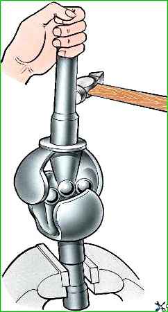
If the opposite ball does not come out of the grooves, press or hit the short fist with a copper hammer (Fig. 6).
Be careful when doing this, as one of the balls may fly out of the hinge at high speed.
- 5. Remove the remaining hinge balls. After selecting new oversized balls (repair) or replacing one of the knuckles, assemble the hinge.
Assemble the hinges in the following order:
- 1. Place your long fist in a vise in a vertical position.
- 2. Insert the center ball.
- 3. Place a short fist on the central ball so that the marks marked with paint coincide and, turning it from side to side, install the three leading (peripheral) balls in turn.
- 4. Spread your fists 10-12 mm and turn the short fist to the maximum angle away from the free grooves, install the fourth ball in the grooves.
- 5. Rotate your short fist into a vertical position. The tension on the hinge balls should be such that the moment required to rotate the fist 10–15° in all directions from the vertical with another fist clamped in a vice is 30–60 Nm (300–600 kgf cm).
The difference in the moments of rotation of the fist in two mutually perpendicular directions of one hinge should not exceed 9.8 Nm (100 kgf cm).
To obtain the required tension and ensure proper assembly, the balls must be sorted into 9 groups.
Dimensions of the diameters of the leading balls of the constant velocity joint in mm:
- First - 25.32–25.34
- Second - 25.34–25.36
- Third - 25.36–25.38
- Fourth - 25.38–25.40
- Fifth - 25.40–25.42
- Sixth - 25.42–25.44
- Seventh - 25.44–25.46
- Eighth - 25.46–25.48
- Ninth - 25.48–25.50
The diameter of the central ball is 26.988 –0.05 mm. Each hinge must be assembled with balls of one group or two adjacent groups.
For example: two balls with a diameter of 25.41 mm and two balls with a diameter of 25.43 mm.
When assembling balls of the same size, be sure to place them diametrically opposite to one another.
The difference in the diameters of two pairs of balls of the same hinge is allowed no more than 0.04 mm.
After assembly, run the joint on the stand for 2 minutes at a rotation speed of 4.8 s–1 (300 min -1) changing the angle from 0 to 30°.
When running in, lubricate the balls and grooves according to the instructions in the lubrication table.
Assembling the front axle
Assemble the front axle in the reverse order of disassembly, taking into account the following:
Press the bushing into the steering knuckle journal flush with the end of the socket under the thrust washer.
After pressing, unfold the sleeve and iron it with a brooch to a diameter of 32 +0.34 +0.17 mm.
Limit the longitudinal movements of the constant velocity joint with thrust washers, one of which is installed in the ball joint and the other in the axle.
The oil grooves of the thrust washers must face the joint.
To secure the washer in the socket, spread it out at 3-4 points evenly spaced around the circumference.
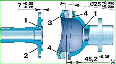
The size from the plane of the thrust washer 1 (Fig. 7) to the flange of the trunnion 2 should be 7 +0.08 –0.26 mm, from the plane of the washer 1 to the center of the ball joint 3 – 48.2 +0.38 mm.
When replacing the bushings of 4 pins in the ball joint, expand them after pressing to a diameter of 25 +0.030 +0.008 mm. A gauge with a diameter of 24.995 mm must fit into both bushings simultaneously.
When installing the hinge, lubricate the ball joint according to the lubrication table.
Lubricate the pins and pin bushings with liquid lubricant before assembly.
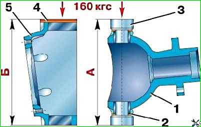
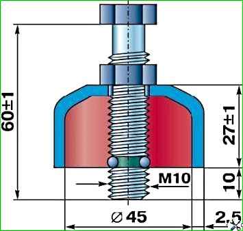
Select the number of spacers to obtain certain axial interference in the pin bushings depending on size “B” (Fig. 8), consisting of the sum of the dimensions of the knuckle and shims, and dimension “A”, consisting of the sum of the dimensions of the ball joint, support washers and kingpins.
The number of gaskets must be at least five. Take measurements under a load of 1.6 kN (160 kgf).
Size “A” should be 0.02–0.10 mm larger than size “B”.
Install the adjusting shims at the top and bottom on the ends of the steering knuckle housing.
If there are an even number of gaskets of equal thickness, install the latter on top and bottom in equal quantities.
With an even number of gaskets, but different thicknesses, or with an odd number of gaskets, the difference between the total thickness of the upper and lower gaskets should not exceed 0.1 mm.
When assembling and installing the ball joint oil seal, soak its inner felt ring in warm engine oil.
After assembly, check the front axle on a stand under load and without it. The load is created by the simultaneous braking of both axle shafts.
A properly assembled front axle should not have increased noise and heating, as well as oil leakage through cuffs and seals, covers and bolted joints.