Procedure for disassembling and assembling carburetors K-151V, K-151E and K-151U
Disassemble the carburetor in the following sequence:
Remove the cotter pin and disconnect the air damper rod from the lever.
Unscrew the seven screws 2 (see Fig. 1) securing the carburetor cover, carefully remove the carburetor cover 4 and the gasket under it.
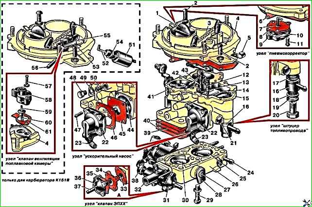
Disassemble the pneumatic corrector diaphragm device; to do this, unscrew three screws 11, remove cover 9, gasket 8, pneumatic corrector diaphragm with rod assembly 7 and spring 10.
Unscrew the screw and remove the accelerator pump nozzle 42.
Unscrew the fuel bypass adjusting screw 43, turn over the body of the float chamber 15 until the ball 13 of the inlet valve falls out.
Unscrew the displacer screw 12.
Unscrew the cylindrical plug and remove the float axis, remove the float and remove the fuel valve.
Unscrew the fuel valve seat together with the gasket.
Unscrew the fuel supply bolt 20, remove the fuel line fitting 16 and the fuel filter 18.
Unscrew the four screws 47 securing the accelerator pump cover, remove the cover 22, gasket 46, accelerator pump diaphragm assembly 45 and spring 44.
Unscrew the removable jets and remove the emulsion tubes.
Unscrew the two screws 29 and disconnect the housing of the mixing chambers 16 from the body of the float chamber 15, being careful not to damage the cardboard 40 and textolite 39 gaskets.
Unscrew the two screws securing the EPHH valve assembly (pos. 31) and remove the latter from the mixing chamber housing.
Unscrew the two screws securing the cover 36 of the EPHH valve, remove the cover 36, cardboard gasket 35 and body 34 of the EPHH valve.
To disassemble the K-151V carburetor, in addition to the above, do the following:
Unscrew the lock 53, disengage the rod 52 from the lever 55 and remove the lever 55.
Unscrew two screws 57, remove cover 58, valve 59, gasket 61 and spring 60. Inspection and inspection of parts
All parts must be clean, free of soot and resinous deposits.
The jets, after washing and blowing with compressed air, must have a given throughput.
All valves must be sealed, the gaskets must be intact and have traces (prints) of the sealing surfaces.
The diaphragms of the accelerator pump, pneumatic corrector and EPH valve must be intact and without damage. Replace faulty or damaged parts with new ones.
Carburetor assembly
The carburetor should be assembled in the reverse order of disassembly.
First you need to assemble all the carburetor body parts - the carburetor cover, the float chamber body and the mixing chamber body, and then connect them together.
During assembly:
Make sure the gaskets are intact and installed correctly.
Make sure that the throttle and air valves turn freely, without jamming and tightly cover their channels.
Tighten all threaded connections snugly, but not overtighten.
Make sure that the fuel valve slides freely in its seat, without distortion or jamming.
Check and, if necessary, adjust the fuel level in the float chamber; the float is up to must rotate freely on its axis without touching the walls of the chamber.
Tighten the screws 47 (see Fig. 1) securing the accelerator pump cover, press the drive lever 23 until it stops, tighten the screws and release the lever.
Tighten the two screws securing the cover 36 of the EPHH valve, pull the locking element 33 of the EPHH valve to a size of 13.5–0.5 mm from plane “A” (see the “EPHH valve” assembly in Fig. 1), tighten the mentioned screws , screw the economizer valve assembly 31 to the mixing chamber housing with two screws.
When assembling, do not mix up the jets.
Check the gap between the mixing chamber wall and the edge of the throttle valve with the primary chamber throttle valve fully open.
The gap must be at least 14.5 mm. If necessary, provide clearance 1 by bending the lever stop.
You can see more details in this article - “Disassembling and assembling the GAZ-2705 carburetor.”
")

")
")
")
")
")
")
")