The non-contact ignition system (Fig. 1) includes the following devices:
– sensor-distributor;
- – transistor switch;
- - ignition coil;
- – additional resistance;
- – emergency vibrator;
- – spark plugs.
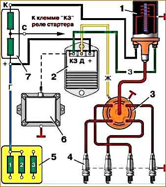
1 - ignition coil; 2 - transistor switch; 3 - sensor-distributor; 4 - spark plug; 5 - fuse block; 6 - emergency vibrator; 7 - additional resistance. Symbol for wire colors: G - blue; K - red; F - yellow; 3 – green
Distributor sensor
The device of the sensor-distributor is shown in Fig. 2.
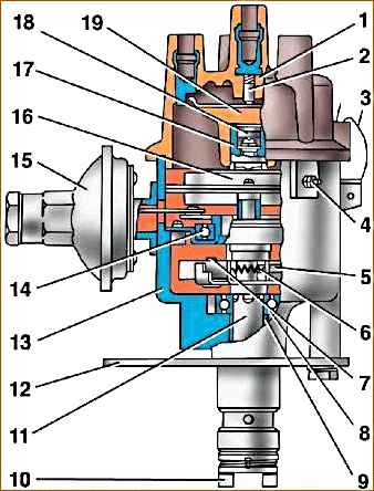
1 - distributor cap; 2 - coal; 3 - cover spring; 4 - low voltage connector; 5 - weight; 6 - spring of the centrifugal machine; 7 - weight axis; 8 - thrust bearing; 9 - roller bearing; 10 - coupling; 11 - roller; 12 - octane corrector plate; 13 - body; 14 - ball bearing; 15 - vacuum regulator; 16 - stator; 17 - rotor bushing; 18 - felt; 19 – slider
The distribution sensor has a housing, a cover, a roller, a sinusoidal voltage sensor, centrifugal and vacuum regulators, as well as an octane corrector.
The centrifugal regulator automatically changes the ignition timing depending on the rotation speed.
The voltage sensor consists of a rotor and a stator.
The rotor is a ring permanent magnet with four-pole cages tightly pressed to it from above and below, rigidly fixed to the bushing.
A runner is installed on the bushing in the upper part of the rotor.
The sensor stator is a winding enclosed in four-pole plates.
The stator has an insulated stranded lead connected to the sensor lead.
The second terminal of the winding is electrically connected to the housing in the assembled sensor-distributor.
There is a mark on the rotor and an arrow on the stator, which serve to set the initial moment of sparking.
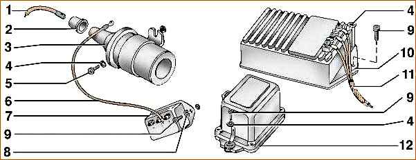
1 - high-voltage wire; 2 - cap; 3 - ignition coil; 4 - washer; 5 - screw; 6 - wire; 7 - additional resistance; 8 - washer; 9 - screw; 10 - transistor switch; 11 - wiring harness; 12 - emergency vibrator
Ignition coil (Fig. 3)
Winding resistance at temperature (25±10) °C, Ohm:
- primary - 0.43
- secondary - 13,000-13,400
Developed secondary voltage maximum - 30000 V
The coil has a high voltage terminal and two low voltage terminals:
- – terminal K – for connection with terminal K of additional resistance;
- – unmarked output – with output K3 of the switch.
Additional resistance (Fig. 3)
The value of active resistance between terminals “+” and “C” is (0.71±0.05) Ohm, between terminals “C” and “K” – (0.52±0.05) Ohm.</p >
Transistor switch (Fig. 3, 4)
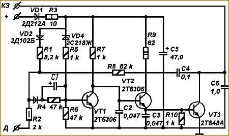
The switch consists of a housing and a board with radio elements.
The switch pins are intended for:
- – terminal D – for connection to the low-voltage terminal of the sensor-distributor;
- – short circuit terminal – for connection to the ignition coil terminal;
- – “+” terminal – for connection to the “+” terminal of the additional resistance or fuse block.
Emergency vibrator (Fig. 1)
It consists of a housing and a board on which all the vibrator components are mounted. Has one output.
It can only be put into operation if the transistor switch or sensor stator coil fails.
Maintenance
After 8,000 km
Check the tightness of the nuts of the low-voltage sensor-distributor connector and the fastening of the connecting wires.
In 16,000 km
Check the ignition distributor sensor: inspect the slider, distributor cap, and if they are dirty, wipe them with a cotton cloth soaked in clean gasoline.
Lubricant Remove the rotor bushing from the dropper (4–5 drops) (first remove the slider and the felt under it).
After 50,000 km
Wash the stator support ball bearing thoroughly with clean gasoline, add Litol-24 lubricant to no more than 2/3 of the free volume of the bearing (first remove the cover, slider, rotor and stator support).
To prevent surface overlap and burnout of the sensor-distributor cover, make sure that the high-voltage wires with tips are inserted into the cover sockets as far as they will go.
Do not turn on the ignition if there is moisture on the cover. Keep plastic parts (cover, slider, low-voltage terminal, etc.) clean.
Procedure for setting ignition timing
- 1. Install the piston of the first cylinder at the top dead center of the compression stroke in the first cylinder until the M3 hole (5° before TDC) on the crankshaft pulley coincides with the pin on the timing gear cover.
- 2. Remove the plastic cover from the distributor sensor.
Make sure that the slider electrode is installed against the terminal on the cover of the distributor sensor marked with the number “1” (terminal for the ignition wire of the spark plug of the first cylinder of the engine).
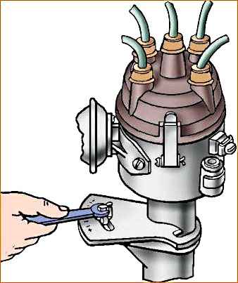
- 3. Tighten the octane corrector plate of the distribution sensor to the drive housing with a bolt with an indicator inserted into it so that the indicator coincides with the middle division of the octane corrector scale.
- 4. Loosen the bolt securing the octane corrector plate to the sensor-distributor body.
- 5. Holding the slider against its rotation with your finger (to eliminate gaps in the drive), carefully turn the housing until the red mark on the rotor and the tip of the petal on the stator are aligned in one line.
Attach the octane corrector plate to the sensor-distributor body with a bolt.
- 6. Install the distributor sensor cover, check the correct installation of the ignition wires to the spark plugs in accordance with the operating order of the engine cylinders 1-2-4-3, counting counterclockwise.
After each ignition installation, check the accuracy of the ignition timing by listening to the engine while the car is moving.
To do this, warm up the engine to a temperature of 80°C and, driving in direct gear on a flat road at a speed of 40 km/h, accelerate the car by sharply pressing the throttle pedal.
If a slight short-term detonation is observed at a speed of 55–60 km/h, then the ignition timing has been set correctly.
In case of severe detonation, turn the housing of the distribution sensor (Fig. 5) on the octane corrector scale by 0.5–1.0 divisions counterclockwise.
Each scale division corresponds to a change in ignition timing by 4°, counting along the crankshaft.
In the complete absence of detonation, it is necessary to increase the ignition timing by turning the sensor-distributor housing clockwise.
")

")
")
")
")
")
")
")