Axles with final drives (Fig. 1 and 2) are installed as a complete set (front and rear) on modifications of vehicles of the UAZ-31512 family with simultaneous replacement of the rear propeller shaft
Maintenance of axles with final drives differs from that described above in the technology of replacing the lubricant in the hinges of the steering knuckles of the front axles, checking and replacing the oil in the final drive housings, as well as adjusting the position of the drive gear 16 of the main gear and its bearings 5 and 7 (see. Fig. 1).
After adjusting the side clearance, it is necessary to check the engagement of the main gear gears along the contact patch, article - "Assembling and adjusting the rear axle of the UAZ-3151"
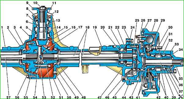
After a mileage of 50,000 km, during the next maintenance, it is recommended to tighten the bolts securing the final drive driven gear 44 and the final drive driven gear 55, as well as the bolts securing the removable bearing housing 25 of the final drive.
The position of gear 16 is adjusted by selecting the adjusting ring 15 of the required thickness.
When replacing the main gears and the large tapered bearing or only the main gears, measure the mounting height of the large tapered bearing 5 under an axial load of 2–2.5 kN (200–250 kgf) and, if it is less than 32.95 mm, by some value, then increase the thickness of the adjusting ring by the same amount compared to that installed in the axle housing.
When replacing only the large tapered bearing 5, so as not to disturb the position of the gear, measure the mounting height of the old and new bearings and, if the new bearing has a larger mounting height than the old one, then reduce the thickness of the adjusting ring 15, and if less, then increase by the difference in bearing heights.
Adjust the tension in bearings 5 and 7 by selecting the adjusting ring 6 and tightening the nut 10.
If this cannot be done, then change the number of shims 13 and again, by selecting the ring and tightening the nut, achieve such a preload of the bearings that there is no axial movement of the gear, and the gear rotates without much effort.
Check with a dynamometer with the rubber cuff 8 removed.
With proper adjustment, when the gear is rotated by the hole in the flange, the dynamometer should show 10–20 N (1–2 kgf) for run-in bearings and 25–35 N (2.5–3.5 kgf) for new ones.
Replace the lubricant in the steering knuckle joints in the following order:
- 1. Disconnect the flexible hose from the wheel cylinder of the brake mechanism and the tie rod ends from the levers, unscrew the bolts securing the ball joint sealing rings and slide the sealing rings onto the ball joint neck (Fig. 2).
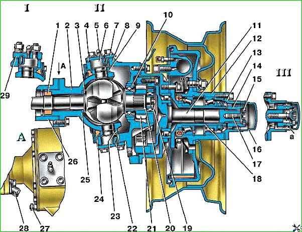
a - signal groove; I - right steering knuckle: II - left steering knuckle; III - wheel release clutch; 1 - oil seal; 2 - ball joint; 3 - steering knuckle hinge; 4 - gasket; 5 - grease fitting; 6 - kingpin; 7 - overlay; 8 - rotary bottle body; 9 - pin bushing; 10 - bearing; 11 - final drive driven shaft; 12 - hub; 13 - drive flange 14 - coupling; 15 - locking ball; 16 - protective cap; 17 - coupling bolt; 18 - axle; 19 - lock nut; 20.23 - support washers; 21 - final drive drive gear; 22 - locking pin; 24 - rubber sealing ring; 25 - thrust washer; 26 - axle housing; 27 - rotation limitation bolt; 28 - wheel rotation limiter; 29 - steering knuckle lever
- 2. Unscrew the nuts of the studs securing the lever or the bolts securing the upper lining of the kingpin and remove the lever or lining and shims.
- 3. Unscrew the bolts securing the lower lining, remove the lining with adjusting shims.
- 4. Use a puller (see Fig. 3) to remove the pivot pins from the steering knuckle housing and remove the housing assembly with the ball joint.
- 5. Carefully, without moving the forks apart (so that the balls do not jump out), remove the joint assembly with bearings and gear from the steering knuckle housing.
You should not remove the joint from the steering knuckle housing unless absolutely necessary and do not disassemble it.
- 6. Remove used grease from the ball joint, joint and housing, rinse thoroughly with kerosene and apply fresh grease.
Perform assembly in the reverse order of disassembly, observing the requirements for adjusting the pins.
When installing the flexible brake hose, do not allow it to twist.
After assembly, bleed the brake drive system (article - "Bleeding the brakes of the UAZ-3151")
Disassemble the final drive in the following order:
- 1. After removing the hub with the brake drum, unscrew the clutch of the brake drive pipeline on the rear brake shield (on the front - a tee of connecting pipes and a flexible hose) from the wheel cylinder, unscrew the nuts of the axle mounting studs and remove the spring washers, oil deflector, axle, axle gasket, spring spacer , brake mechanism assembly and brake shield gaskets.
- 2. Unscrew nut 45 (see Fig. 1) securing the bearing on the final drive driven shaft, unscrew the bolts securing the final drive housing cover, remove the cover assembled with the shaft, remove the cover gasket and press the shaft out of the cover.
- Unlike the left final drive, shaft 39 and nut 45 of the right gear have a left-hand thread. The nut with a left-hand thread is marked with an annular groove, and the shaft is marked with a blind drilling with a diameter of 3 mm in the end of the splined end.
- 3. Unscrew the driven gear mounting bolts and remove the gear from shaft 39.
- 4. Mark the position of the roller bearing housing 25 on the final drive housing boss of the rear axle, unscrew the housing mounting bolts, and remove the bearing housing.
Do not remove the front axle final drive roller bearing housing unless absolutely necessary. (For further procedure for disassembling the final drive of the front axle, see above in the description of replacing the grease in the steering knuckle joints.)
Remove the retaining ring 22 of the ball bearing 21, the axle shaft 18 and the oil deflector 20 from the final drive housing.
- 5. Remove the roller bearing retaining ring 26, roller bearing 25, drive gear 47 and ball bearing from the axle shaft.
Assemble the final drive in the reverse order of disassembly, taking into account the following:
- - bearing mounting nut 45 (Fig. 1) on the driven shaft of the front and rear final drives, as well as nut 19 (see Fig. 2) securing the bearing and gear on the drive shaft of the front final drive, after tightening, spread into the groove of the shaft, and compress the rings 26 for locking the bearings on the axle shafts of the rear final drives after installation in the groove;
- - tighten the bolts for fastening the wheel (driven gear) and the removable bearing housing to a torque of 64–78 Nm (6.5–8.0 kgf m), bolts for fastening the crankcase cover – 35–39 Nm (3.6–4. 0 kgf m).
")

")
")
")
")
")
")
")