Replace piston rings after 70,000–90,000 km (depending on vehicle operating conditions)
Piston rings are installed three on each piston: two compression rings and one oil scraper ring.
Compression rings are cast from special cast iron.
The outer surface of the upper compression ring is coated with porous chrome, and the surface of the second compression ring is tin-plated or has a dark phosphate coating.
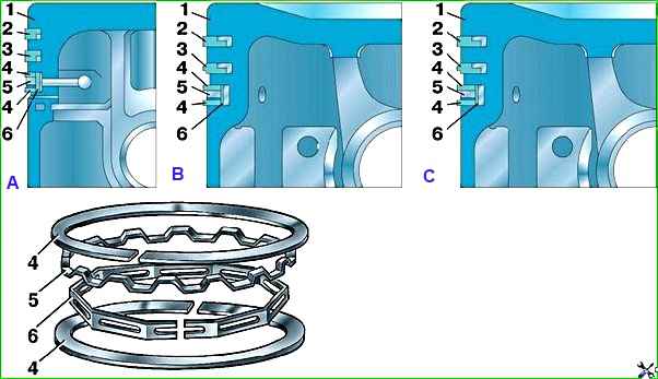
There are grooves on the inner cylindrical surfaces of both compression rings (Fig. 1, A), due to which the rings are slightly turned out when the piston moves downwards, which helps to better remove excess oil from the surface of the liners.
The rings must be installed on the piston with the grooves upward, towards the piston bottom.
The UMZ-4218.10 engine can be equipped with two versions of compression rings (Fig. 1, B, C).
One version of the upper compression ring 2 (Fig. 1, B) has a groove on the inner cylindrical surface.
The ring must be installed on the piston with the groove facing up.
Another version of the upper compression ring 2 (Fig. 1, C) has a barrel-shaped profile of the outer surface, there is no groove on the inner cylindrical surface of the ring.
The position of the ring when installed in the piston groove is indifferent.
The lower compression ring 3 (Fig. 1, B, C) is of the scraper type, on the lower end surface it has an annular groove, which, together with the conical outer surface, forms a sharp lower edge (“scraper”).
The ring is made in two versions - with a groove on the inner cylindrical surface of the ring (Fig. 1, B) and without a groove (Fig. 1, C).
The ring must be installed on the piston with the sharp edge “scraper” down.
The oil scraper ring is composite, has two annular disks, radial and axial expanders.
The outer surface of the oil ring disc is coated with hard chrome. The ring lock is straight.
Piston rings of repair sizes (see Table 2) differ from rings of nominal sizes only in their outer diameter.
Rings of the repair size can be installed in worn cylinders with the next smaller repair size by filing their joints to obtain a gap in the lock of 0.3–0.5 mm (0.3–0.65 mm for engines mod. 4218).
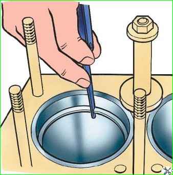
Check the side clearance at the joint of the ring as shown in Fig. 2.
For reground cylinders, fit the rings along the top part, and for worn cylinders, fit them along the bottom part of the cylinder (within the stroke of the piston rings).
When adjusting, install the ring in the cylinder in the working position, i.e. in a plane perpendicular to the cylinder axis, to do this, move it in the cylinder using the piston head.
The planes of the joints when the ring is compressed must be parallel.
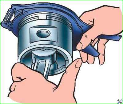
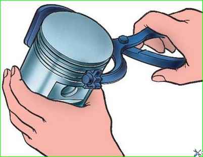
Remove and install rings on the piston using the tool (Fig. 3) model 55-1122.
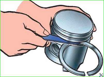
After adjusting the rings to the cylinders, check the lateral clearance between the rings and the grooves in the piston (Fig. 4), which should be:
- - for the upper compression ring 0.050–0.082 mm,
- - for lower compression – 0.035–0.067 mm.
For large gaps, replacing only the piston rings will not eliminate increased oil consumption due to intensive pumping of oil by the rings into the space above the piston.
In this case, replace the pistons at the same time as replacing the rings.
Simultaneous replacement of piston rings and pistons dramatically reduces oil consumption.
When replacing only the piston rings without replacing the pistons, remove carbon deposits from the piston crowns, the annular grooves in the piston head and the oil drain holes located in the oil ring grooves.
Remove carbon deposits from the grooves carefully, so as not to damage their side surfaces, using a device (Fig. 5).
Remove carbon deposits from the oil drain holes using a drill with a diameter of 3 mm.
When using new or oversize cylinder liners, the top compression ring must be chrome-plated and the remaining rings must be tin-plated or phosphated.
If the liner is not being repaired, but only the piston rings are changed, then all of them must be tinned or phosphated, since a chrome-plated ring is very poorly bonded to a worn liner.
Before installing the pistons into the cylinders, spread the joints of the piston rings at an angle of 120° to each other.
After changing the piston rings, within 1000 km, do not exceed the vehicle speed of 45 - 50 km/h.