Removal, disassembly and assembly of springs for cars of the UAZ-31512 family
Remove the front spring in the following order:
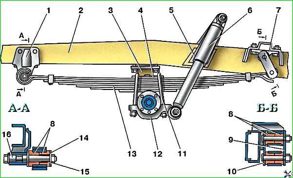
Unscrew the nuts of the stepladders 11 (see Fig. 1) of the springs, remove the stepladders, lining 12 and lining 4.
Place the front of the car on a stand.
Unscrew the bracket fastening bolts 7 and the axle nut 16 of the spring eye.
Remove spring 13 and disassemble the earring with rubber bushings 8.
Install the spring in reverse order.
Remove and install the rear spring in the same way as the front one.
When installing front and rear springs on a vehicle, the folded tabs on the first two leaves must face forward.
Final tightening of the nuts of the spring ladders is carried out with the springs loaded.
Disassemble the spring in the following order:
Secure the spring in a vice to the head of the center bolt.
Bend the spring clamps.
Unscrew the center bolt nut and disassemble the spring. After disassembling, thoroughly clean the sheets from dirt, rinse in kerosene, replace broken sheets.
Assemble the spring in reverse order, taking into account the following:
Before assembly, lubricate the spring leaves according to the instructions in the lubrication table.
Rivet the clamps securely to the sheets; the ends of the rivets of the clamps should not protrude above the surface of the sheets.
After assembling the spring, the clamps should not interfere with the free movement of the sheets during operation.
After assembly, paint the spring.
Features of disassembling the front spring suspension
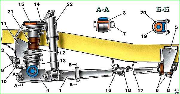
Replacing springs 12 (see Fig. 2), vibration-absorbing pads 15 and buffers 21:
Disconnect the lower shock absorber eyes 22 from the longitudinal rods 1 by unscrewing the nuts and removing the bolts.
Lift and place the front of the car on a stand.
Remove springs 12 and vibration-absorbing pads 15.
Unscrew the bolts securing the buffers 21.
Assemble in reverse order.
If it is impossible to remove or insert the spring, you must additionally disconnect one of the ends of the transverse rod.
Replacement of rubber-metal hinges 3, support bushings 6 of the longitudinal rods and rubber bushings 18, 19 of the stabilizer:
Securely secure the car from spontaneous movement.
Disconnect the lower shock absorber eyes from the longitudinal rods by unscrewing the nuts and removing the bolts.
Unscrew nuts 7 and knock out the bolts securing the longitudinal rod to the bridge.
Unscrew and unscrew nuts 8.
Unscrew the stepladder nuts 20 securing the stabilizer to the rod.
Remove the longitudinal rods by moving the rear end of the rod out of the bracket hole on the frame.
Unscrew the bolts securing the stabilizer to bracket 17.
Replace rubber-metal hinges 3. Replacement of hinges is carried out using special mandrels on pressing equipment. All hinges should be replaced at the same time.
Remove bushings 19 from the stabilizer and put on new ones.
Replace bushings 18 and tighten the bolts securing the stabilizer to the bracket 17.
Put the washer and support rubber hinge 6 on the rear end of the rod 1, insert the rod into the hole in the bracket 5, put on the second rubber hinge and washer, and tighten the nut 8.
Insert the front end of the rod into bracket 4, install new bolts and tighten nuts 7.
Install the second rod in the same way.
Tighten nuts 7 to a torque of 14–16 kgf m. Tighten nuts 8 until they stop and secure them.
Install stepladders 20 for attaching the stabilizer to the rod and tighten the nuts of the stepladders.
Connect the lower shock absorber eyes to the longitudinal rods by inserting the bolts and tightening the nuts.
Replacing transverse link 2 or rubber-metal joints 9:
Unscrew the bolt and nut securing the truss rod to the bridge and frame.
Remove the cross rod.
Replace the hinges, similar to the hinges of the longitudinal rods.
Install the rod and secure it using new bolts.
Tighten the nut and bolt to a torque of 14–16 kgf m.
Removal, disassembly and assembly of springs for cars of the UAZ-3741 family
Remove the springs in the following order:
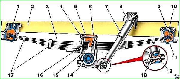
Unscrew the nuts of the stepladders 16 (see Fig. 5) of the springs, remove the stepladders, pad 14 and pad 4 of the springs.
Disconnect the lower shock absorber eye.
Place the front of the car on a stand.
Unscrew the bolts securing the covers of brackets 1 and 9 and remove the covers.
Remove the springs with rubber cushions.
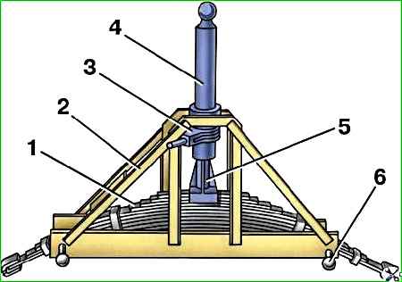
Install the springs in the reverse order. At the same time, straighten the spring using a special device (Fig. 6).
In the absence of a special device, we recommend installing the spring in the following order:
Secure the springs with stepladders to the bridge.
Install the spring pads on its ends.
Gradually lowering the car onto the axle with springs and guiding the springs with a lever, ensure that the ends of the spring with cushions are installed alternately in its brackets.
Install the bracket covers and tighten the mounting bolts.
Remove and install the rear spring in the same way as the front one.
Disassemble the spring in the following order:
Secure the spring in a vice to the head of the center bolt.
Bend the spring clamps.
Unscrew the center bolt nut and disassemble the spring. After disassembling, thoroughly clean the sheets from dirt, rinse in kerosene, replace broken sheets.
Assemble the spring in reverse order, taking into account the following:
Before assembly, lubricate the spring leaves according to the instructions in the lubrication table.
The selected sheets must have reinforced cups on the main sheets and clamps.
Rivet the clamps securely to the sheets; the ends of the rivets of the clamps should not protrude above the surface of the sheet.