Maximum permissible wear of the main associated engine parts
Mating of wearing parts is carried out mainly with replaceable parts, which allows you to repair the cylinder block by regrinding or replacing liners, replacing worn camshaft bushings with semi-finished ones and then processing them to the required size, replacing crankshaft main bearing shells.
Restoring the functionality of the cylinder block hole-pusher pair due to minor wear comes down to replacing the pushers.
Repair and replacement of cylinder block liners
The maximum allowable wear of cylinder liners should be considered to be an increase in the gap between the liner and the piston skirt to 0.3 mm.
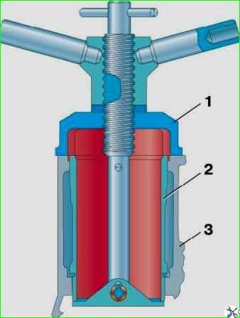
If there is such wear, press the liner out of the cylinder block using puller 1 (Fig. 1) and bore it to the nearest repair size of the piston with a processing tolerance of +0.06 mm.
Do not clamp the sleeve into the jaw chuck when processing, as this will cause deformation of the sleeve and distortion of its dimensions.
Secure the sleeve in a device, which is a sleeve with seating belts with a diameter of 100 and 108 mm.
Insert the sleeve into the sleeve until it stops at the upper collar, which is clamped with an overlay ring in the axial direction.
After processing, the liner cylinder mirror should have the following deviations:
- 1. Ovality and taper are not more than 0.01 mm, and the larger base of the cone should be located in the lower part of the sleeve.
- 2. Barrel-shaped and corseted - no more than 0.08 mm.
- 3. The runout of the cylinder mirror relative to the seating belts with a diameter of 100 and 108 mm is no more than 0.01 mm.
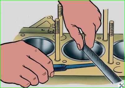
After pressing the liner into the cylinder block, check the amount of protrusion of the upper end of the liner above the upper plane of the block (Fig. 2).
The amount of protrusion should be 0.005–0.055 mm.
If the protrusion is insufficient (less than 0.005 mm), the head gasket may be punctured; in addition, coolant will inevitably enter the combustion chamber due to insufficient sealing of the upper flange of the liner with the cylinder block.
When checking the amount of protrusion of the end of the sleeve above the block, it is necessary to remove the rubber sealing ring from the sleeve.
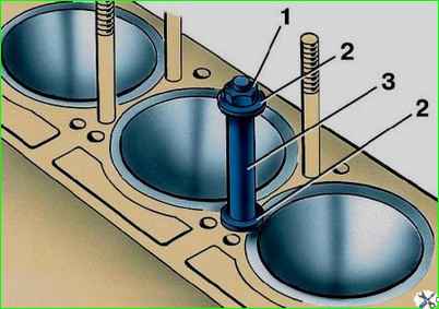
To prevent the liners from falling out of their sockets in the block during repairs, secure them using washers 2 and bushings 3, placed on the cylinder head mounting studs, as shown in Fig. 3.
Cylinder liners, bored to the third repair size of the piston, after wear, replace with new ones.
Table 1
Mating parts - Maximum permissible clearances and ellipse and taper - Place and method of measurement
Cylinder - piston:
- Maximum permissible gap 0.3 mm
- Measure the cylinder in two mutually perpendicular directions (along the axis of the crankshaft and perpendicular to it) and in two zones (at a distance of 8-10 mm and 60-65 mm) from the upper plane of the block.
- Take the largest size.
- Measure the piston at a distance of 5-10 mm from the bottom of the skirt in a plane perpendicular to the axis of the piston pin
Main and connecting rod journals of the crankshaft - liners:
- Maximum permissible gap 0.15 mm
- Measure as indicated in the article - “Repair of the UAZ-3151 crankshaft”
Crankshaft journal:
- Maximum permissible ellipse and taper - 0.07 mm
- Measurement and method - Along the axis of the crankshaft and perpendicular to it
Crankshaft connecting rod journal:
- Maximum permissible ellipse and taper - 0.05 mm
- Measurement and method - Along the axis of the crankshaft and perpendicular to it
Crankshaft axial clearance:
- Maximum permissible gap 0.25 mm
- Measure with a feeler gauge in several places around the circumference
Camshaft axial clearance:
- Maximum permissible gap 0.25 mm
- Measure with a feeler gauge in several places around the circumference
Axial clearance of connecting rod:
- Maximum permissible gap 0.5 mm
- Measure with a probe in several places around the ugliness
Cylinder block - pusher:
- Maximum permissible gap 0.1 mm
- Measure in two zones along the length of the working surface
Valve - guide sleeve:
- Maximum permissible gap 0.25 mm
- Measure in two zones along the length of the working surface
Camshaft journal - bushing:
- Maximum permissible gap 0.15 mm
- Measure in two zones along the length of the working surface
Camshaft journal:
- Maximum permissible ellipse and taper - 0.05 mm
Piston pin - connecting rod upper head bushing:
- Maximum permissible gap 0.10 mm
- Measure in two zones along the length of the working surface
Piston pin - piston:
- Maximum permissible gap 0.10 mm
- Measure in two zones along the length of the working surface
Conrod upper end bushing:
- Maximum permissible ellipse and taper 0.02 mm
- Measure along the axis of the connecting rod and perpendicular to it
Piston pin:
- Maximum permissible ellipse and taper 0.01 mm
- Measure along the axis of the connecting rod and perpendicular to it
Piston ring - groove in the piston (height):
- Maximum permissible gap 0.15 mm
- Measure with a feeler gauge at several points around the circumference
Piston ring - gap in the lock
- Maximum permissible gap 3.0 mm
Table 2. Size groups of pistons
Designation of size group - Maximum deviations of the skirt diameter, mm:
A
- 0.000
- -0.012
B
- +0.012
- 0.000
B
- +0.024
- +0.012
G
- +0.036
- +0.024
D
- +0.048
- +0.036
")

")
")
")
")
")
")
")