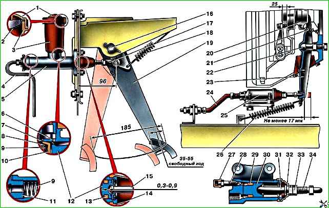
The hydraulic clutch release (Fig. 1) of vehicles of the UAZ-31512 family consists of a suspended pedal 19, a master cylinder 5, a hydraulic pipe 4, a hydraulic hose 24 and a working cylinder 25
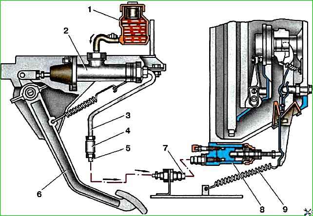
The hydraulic clutch release mechanism for vehicles of the UAZ-3741 family is similar and is shown in Fig. 2.
Maintenance of the hydraulic drive consists of maintaining the level of working fluid in the tank 15–20 mm below the upper edge of the filler hole, adjusting the free play of the clutch pedal and, if necessary, bleeding it.
In the hydraulic clutch drive, only the free play of the outer end of the clutch release fork is adjusted, which should be 2.5–3.6 mm.
This corresponds to a gap of 1.7–2.5 mm between the release levers and the clutch release bearing and a free play of the clutch pedal “A” of 35–55 mm for all vehicles.
Adjustment is made by changing the length of the pusher of the clutch release cylinder.
Before adjusting the free travel of the clutch pedal, check the full travel of the clutch pedal (all the way to the floor), which should be 185 mm for vehicles of the UAZ-31512 family and 200 mm for vehicles of the UAZ-3741 family.
If necessary, make adjustments by changing the length of the pusher of the clutch master cylinder.
Removing and disassembling the hydraulic clutch
Remove the hydraulic clutch release drive from the vehicle in the following order:
- – disconnect the hydraulic hose from the working cylinder;
- – drain the fluid from the hydraulic drive through the disconnected end of the hydraulic hose;
- – remove the release spring of the clutch release fork;
- – disconnect and remove the working cylinder;
- – remove the clutch release pedal release spring;
- – unscrew and remove the master cylinder pusher fork pin;
- – disconnect and remove the main cylinder. On vehicles of the UAZ-3741 family, first disconnect the tank from the flexible hose.
Disassemble the master cylinder in the following order:
- – remove the cover and mesh filter of the filling tank (vehicles of the UAZ-31512 family);
- – unscrew the tank mounting fitting (vehicles of the UAZ-31512 family);
- – unscrew the housing of the flexible hose fitting of the tank (vehicles of the UAZ-3741 family);
- – remove the retaining ring and thrust washer from the master cylinder body;
- – remove the piston with sealing collars and the return spring from the body.
To avoid damage to the sealing collars, when removing the piston, apply compressed air to the hole for the hydraulic tube.
The main cylinder fittings with gaskets should not be unscrewed during disassembly if no leakage of working fluid has been observed through them.
Disassemble the working cylinder in the following order:
- – disconnect the rubber protective cap from the working cylinder and remove the pusher along with the cap;
- – remove the cap from the pusher;
- – remove the retaining ring from the working cylinder body;
- – remove the piston with the sealing lip from the working cylinder; To avoid damage to the piston and cuff, supply compressed air to the hole for the hydraulic hose;
- – remove the sealing collar from the piston;
- – unscrew the bleeder valve;
- – remove the protective cap from the valve.
Wash the hydraulic drive parts thoroughly in brake fluid or alcohol, blow with compressed air and inspect.
Assessment of the technical condition of hydraulic drive parts
All rubber seals must be soft and elastic. Hardened Replace cuffs that are swollen or have tears or cracks on the working surfaces.
The mirrors of the working and master cylinders should be free of marks, holes, burrs and significant wear.
Small traces of corrosion and minor wear can be eliminated by grinding or honing to a diameter of no more than 25.15 mm for the working cylinder and 22.2 mm for the main cylinder, subject to the mandatory use of only new seals.
Assembling the hydraulic clutch
Assemble the clutch release hydraulic drive in the reverse order of disassembly.
Before assembly, lubricate the cylinder mirror with castor oil or fresh brake fluid.
When assembling the master cylinder, make sure that the return spring confidently returns the piston to its original position.
Check with a soft wire with a diameter of 0.3–0.5 mm whether the cuff does not block the compensation hole, which is completely unacceptable.
When assembling the working cylinder, make sure that the tension spring confidently moves the piston in the cylinder. Install the hydraulic drive on the vehicle in the reverse order of removal.