Disassemble the generator in the following order:
- 1. Remove the brush holder with brushes
- 2. Remove the bearing cover and unscrew the nut securing the rear end of the rotor shaft
- 3. Unscrew the generator coupling screws and remove the rear cover with the stator.
- 4. Disconnect the phase ends of the stator winding from the rectifier unit and remove the stator.
- 5. Remove the pulley, fan, key and spacer from the rotor shaft.
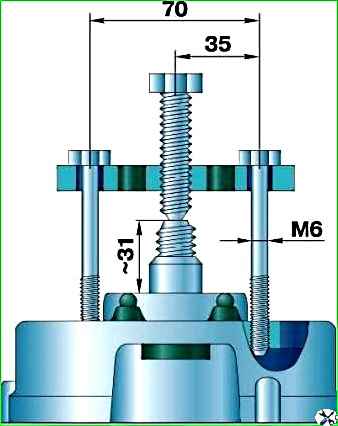
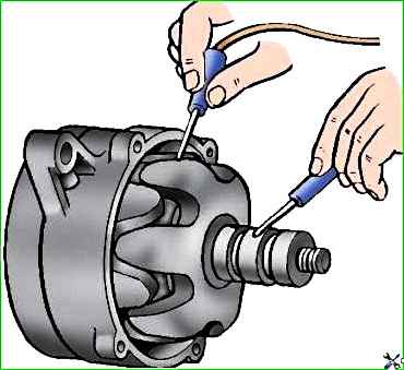
- 6. Remove the front cover along with the bearing from the rotor shaft using the threaded holes in the cover and a special tool (Fig. 1).
Inspect and check the parts and components of the generator
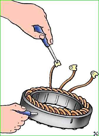
Then, using a test lamp, check whether there is a short circuit in the stator windings between the turns.
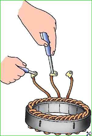
To do this, connect the test lamp alternately to the two terminal tips of each winding (Fig. 3); If the winding is working properly, the lamp should light.
If the lamp does not light between any two terminals, this indicates a break in the winding or a connection failure at the midpoint of the phases.
There should be no traces of contact with the rotor at the stator poles.
If there is any interference, check the covers and bearings and replace if necessary.
Lids
When inspecting, pay attention to the absence of damage to the covers, especially at the locations of the mounting feet.
The bearing should fit into the back cover (from the slip ring side) freely, but without noticeable slack.
The diameter of the bearing hole should be 35+0.03 mm.
If the diameter of the bearing hole is higher than specified, then the cover must be replaced.
Make sure the bearing in the front cover (pulley side) is seated tightly (press fit).
The diameter of the bearing hole should be 47+0.03 mm
Rotor
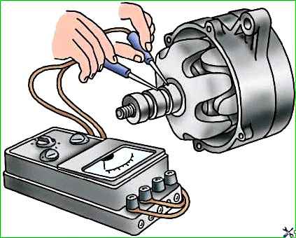
Check with an ohmmeter whether there is a short circuit between the turns in the rotor winding (Fig. 4) and a short circuit of the winding to the housing (Fig. 5). If damaged, replace the rotor
If the rotor slip rings are dirty, have burn marks and uneven wear across their width, clean them with fine glass sandpaper, 80 or 100 grit.
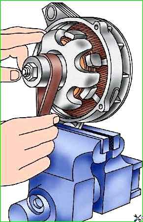
To clean the slip rings, secure the generator to the front cover in a vice and, smoothly turning the rotor, sand the rings with sandpaper, as shown in Fig. 6.
If the rings have severe wear and surface runout, grind and grind them (for the G250P2 generator, the minimum permissible groove diameter for slip rings is 29.2 mm).
The surface roughness of the rings must be class 7
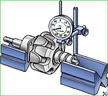
After grooving, check the runout of the slip rings with an indicator (Fig. 7).
Ring runout of more than 0.08 mm leads to their rapid burning and wear of the brushes, especially at high rotation speeds.
Brush assembly
Check whether the brushes are stuck in the brush holders, as well as the condition and amount of wear of the brushes, and the tension of the brush springs.
When the brushes are pressed lightly, the sparking increases and the rings burn.
Excessive pressure on the brushes causes increased wear.
The pressing force of the brushes should be within the limits 180–260 gs.
Make sure that the brushes in the brush holders move freely, without jamming or excess play.
Even slight sticking of the brushes, which is sometimes difficult to detect, increases sparking underneath them.
Brushes worn to a height of 8 mm or damaged, replace with new ones of type M1. Do not use any other type of brush
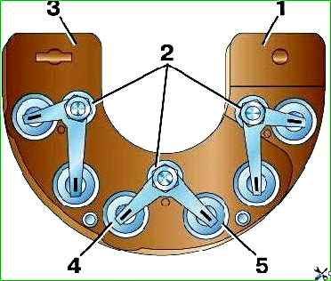
Clean the rectifier block VBG-1 (or PBB-4-45) (Fig. 8) thoroughly from dirt.
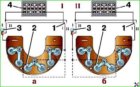
Check the diodes using test lamp 3 (Fig. 9).
Due to the fact that diodes of different polarities are mounted in each section of the block, check them with different polarities (Fig. 9, a, b) when the battery is turned on.
If the diode is working properly, in the switch position “Ι” the lamp should light up, but in the “ΙΙ” position it should not light up.
If the lamp does not light up in the “Ι” position, this indicates a break in the diode transition.
If the control lamp in the "ΙΙ" position of the switches is on, this indicates a short circuit in the diode.
Replace the rectifier section with a faulty diode.
Solder the leads of the rectifier section with two soldering irons simultaneously with the nut of the phase winding connection terminal unscrewed.
When installing a new section, keep in mind that the soldering area can be heated to no more than 150 °C for five seconds.
Do a more thorough check of the diodes using a special device for testing semiconductor devices.
Assemble the generator in reverse order.
Generator check
Determine the serviceability of the generator and the correctness of its assembly by checking the rotor speed at which a voltage of 12.5 V is reached when the generator is operating without load and at full load.
Carry out the check on a test bench consisting of an electric motor that allows you to smoothly change the frequency of dyeing of the generator up to 3000 min -1, a rheostat that allows you to create a load of up to 40 A in the generator circuit, a 6ST-60- battery EM, rheostat in the excitation winding circuit at 3–5 A and devices
You can use the control and test bench model 533 GARO
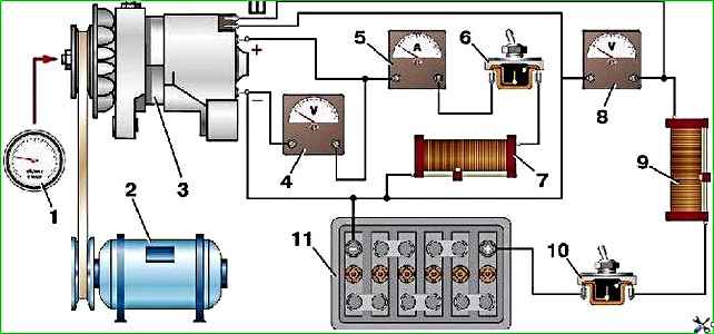
The generator test circuit on a simple stand is shown in Fig. 10.
To check the generator, turn on switch 10 and use rheostat 9 to adjust the voltage to 12.5 V using voltmeter 8.
Without load (switch 6 is off), when the generator is cold, voltmeter 4 should show 12.5 V at a rotor speed of no more than 900 min -1.
Then turn on switch 6 and increase the load by increasing the generator rotor speed.
With a load of 28 A and a voltage of 12.5 V (according to voltmeter 4), the rotor speed should be no more than 2100 min -1 .
During these tests, use a rheostat to maintain the voltage at terminal “Ш” within 12.5 V (according to voltmeter 8). Generators 665.3701–01 and 161.3771
Disassemble the generator 665.3701–01 in the following order:
- 1. Unscrew the nuts securing the positive terminal of the generator and disconnect the terminal of the capacitor.
- 2. Unscrew the two screws securing the casing to the cover.
- 3. Separate the casing from the cover by disconnecting the wires with plugs from the generator.
- 4. Unscrew the screw securing the brush holder and remove it.
- 5. Unscrew the four nuts of the coupling screws and remove the cover from the slip ring side along with the stator.
- 6. Unscrew the three nuts securing the different terminals from the rectifier block and separate the stator from the cover.
- 7. Unscrew the pulley mounting nut.
- 8. Remove the pulley, knock out the key.
- 9. Remove the drive side cover along with the bearing from the rotor shaft.
If it is necessary to replace the voltage regulator, remove the two screws securing the voltage regulator to the casing, and then the two screws securing the voltage regulator to the insulating base July.
If it is necessary to separate the rectifier block from the cover, unscrew the contact bolt, the positive terminal nut, three screws securing the block to the cover and disconnect the block terminal from the block plug.
Inspect and check the parts and components of the generator.
Assemble the generator in reverse order.
Disassembly and assembly of generator 161.3771 are similar.
The main difference is the absence of a rear protective cover.
The voltage regulator is located in the brush holder housing.
Brush assembly
Make sure that the brushes are intact, do not jam in the brush holders and are in secure contact with the slip rings. If the brushes are worn out, replace them.
Before installing the brush holder in place, blow out the socket in the generator.
Rectifier block
Operations and techniques for checking the rectifier unit are similar to the VBG-1 rectifier unit described above.
Capacitor
The capacitor is used to protect the vehicle's electronic equipment from voltage pulses in the ignition system, as well as to reduce interference with radio reception.
If there is a radio receiver in the car, damage to the capacitor or loosening of its fastening on the generator (deterioration of contact with ground) is detected by an increase in interference to radio reception when the engine is running.
The approximate serviceability of the capacitor can be checked with a megger or tester (on a scale of 1–10 mOhm).
If there is no break in the capacitor, then at the moment the probes of the device are connected to the terminals of the capacitor, the arrow should deviate in the direction of decreasing resistance, and then gradually return back.
The capacitance of the capacitor, measured with a special device, should be 2.2 μF ± 20%.
Lids
When inspecting, pay attention to the absence of damage to the covers, especially at the locations of the mounting feet and bearing seats.
Replace damaged covers.
Generator check
To determine operability and compliance with technical specifications, the generator is checked on a stand according to the diagram shown in Fig. 11. Turn on the electric motor of the stand.
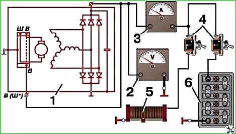
The check is carried out immediately after the generator has operated for 1.5 hours at a generator rotor speed of 3000 min -1, a load current of 40 A and a voltage of 13 V with the switches on.
When testing, gradually increase the rotor speed until the voltage on the voltmeter reaches 13 V.
A working generator must have a return current strength of at least 55 (57*) A at a rotor speed of 5000 min -1. (* For generator 161.3771)
If the measured value of the supplied current is less, this indicates a malfunction in the stator and rotor windings, damage to the valves or wear of the slip rings and brushes.
In this case, a thorough check of the windings and diodes is necessary to determine the location of the fault.
The voltage at the generator output is checked at the rotor speed (3500±125) min -1.
The generator current is maintained using a rheostat equal to (18±0.9) A.
Measure the voltage at the generator output, which should be within the limits specified in the technical data for this type of generator.
If the voltage does not fall within the specified limits, then replace the voltage regulator with a control one that is known to be good, and repeat the test.
If the voltage still does not fall within the specified limits, then it is necessary to check the windings and diodes of the generator.
")

")
")
")
")
")
")
")