Assemble the differential in the following order:
- 1. Before assembling the differential, lubricate the axle gears, pinions, thrust washers and pinion axles with transmission oil
- 2. Install thrust washers on the journals of the axle shaft gears.
- 3. Install the axle gear with thrust washer assembly into the left gearbox.
- 4. Install the satellites on the axis of the split cross.
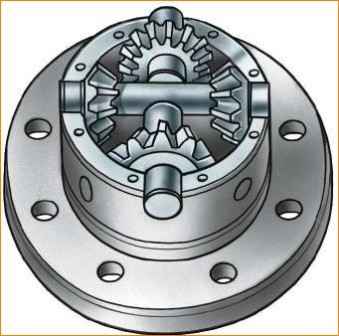
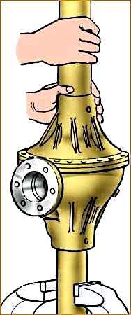
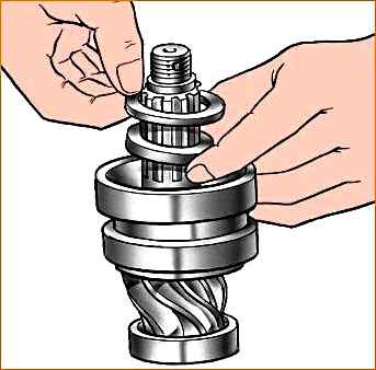
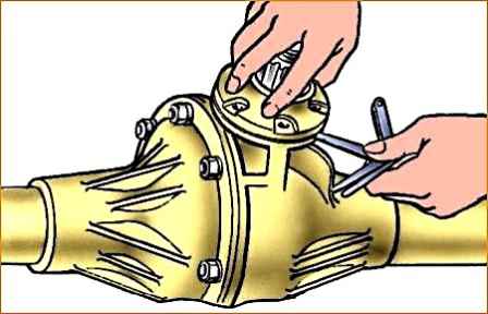
- 5. Install the detachable crosspiece (Fig. 1) with satellites into the left satellite box.
- 6. Install the axle gear with thrust washer assembly into the right gearbox.
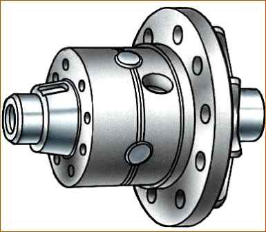
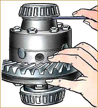
Holding the axle gear, install the right satellite cup onto the left one so that the marks (Fig. 2) (ordinal numbers) of both cups are aligned.
- 7. Connect the halves with bolts and tighten them. Tightening torque 32–40 Nm (3.2–4.0 kgf).
- 8. Install the main drive driven gear onto the gearbox, aligning the bolt holes. Install the bolts and tighten them.
Tightening torque 98–137 Nm (10–14 kgcm).
For the assembled differential, the axle gears must be rotated using a splined mandrel from a force of no more than 59 N (6 kgf) applied over a radius of 80 mm.
Adjust the differential bearings (if they are replaced) in the following order:
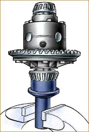
- 1. Press the inner rings of the bearings (Fig. 3) of the differential onto the journals of the assembled differential so that there is a gap of 3.5–4.0 mm between the ends of the gearbox and the ends of the inner rings of the bearings.
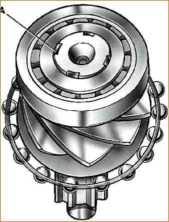
- 2. Install the differential assembly into the crankcase, then the gasket and crankcase cover and, turning the cover by the casing, roll the bearings so that the rollers are in the correct position (Fig. 4).
Then use bolts and nuts to evenly connect the cover to the crankcase.
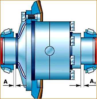
- 3. Unscrew the bolts again, carefully remove the cover, remove the differential from the crankcase and use a feeler gauge to measure the gaps A and A1 (Fig. 5 and 6) between the ends of the inner rings of the bearings and the gearbox.
- 4. Select a package of gaskets with a thickness calculated according to the formula:
- s = A + A1 + 0.1, where: s – thickness of the gasket package, mm;
- A and A1 – gaps between the ends of the inner rings of bearings and the satellite box, mm;
- 0.1 – constant value (to ensure preload), mm.
- 5. Remove the differential bearing inner races. Divide the selected pack t gaskets approximately in half.
Install the gaskets on the journals of the satellite gearbox and press the inner rings of the bearings until they stop.
Assemble and adjust the drive gear bearings in the following order:
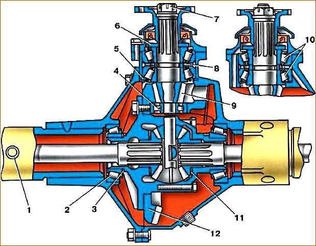
- 1. Press the bearings onto the drive gear. After pressing on the rear support bearing with cylindrical rollers, open the end of the shank onto which it is pressed (Fig. 7).
Place the spacer sleeve (Fig. 8) and adjusting shims for the front bearing (double-row bevel) of the drive gear between the inner rings.
- 2. Install adjusting ring 5 (see Fig. 20) of drive gear 9 (not installed since 1991).
- 3. Press the drive gear assembly with bearings into the crankcase as far as it will go and adjust the front bearing preload by changing the thickness of the shim pack 8 and tightening the nut 7 until it stops.
In this case, the oil removal ring 6 and the flange must be installed on the gear shaft, and the front bearing cover must be removed so that the friction of the cuff on the flange does not affect the measurement readings.
To reduce the tension, add spacers, to increase it, remove it.
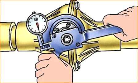
With proper adjustment, there should be no axial play, and the spring dynamometer should show a force of 15–30 N (1.5–3 kgf) for run-in bearings and 20–35 N (2.0–3.5 kgf) for new bearings when turning the gear by the hole in the flange (Fig. 9).
- 4. After completing the adjustment, remove the flange and install the gaskets and front pinion bearing cap.
Secure the cover with bolts. Place the flange, tighten nut 7 (see Fig. 20) and secure it with a cotter pin. Tightening torque 167–206 Nm (17–21 kgf m).
Adjust the side clearance and the position of the main gear gears after adjusting the bearings of the drive gear and differential in the following order:
- 1. Install the differential with the adjusted bearing assembly into the crankcase.
Install the gasket on the plane of the crankcase connector with the cover. Install the crankcase cover and secure with bolts.
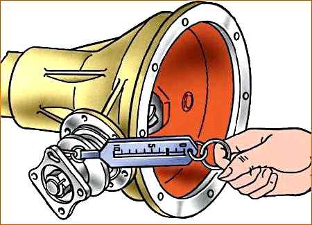
2. Measure the lateral clearance between the teeth of the drive and driven gears, which should be 0.2–0.6 mm.
Make measurements on the drive gear flange at a radius of 40 mm (Fig. 10).
Adjust the side clearance by moving shims 3 (see Fig. 20) from one side of the differential box to the other.
If you remove shims from the side of the driven gear, the gap in the mesh increases, but if you add shims, the gap decreases.
Rearrange the spacers without changing their quantity, as this will disrupt the tension of the differential bearings.
- 3. On axles with an adjusting ring 5 (see Fig. 20), check the engagement of the gears along the contact patch.
To do this, paint the teeth of the driven gear with paint.
Keep in mind that very liquid paint spreads, and if it is too thick, it cannot be squeezed out of the spaces between the teeth.
Then, using the axle shafts, slow down the driven gear and rotate the drive gear in both directions until a clear contact patch is identified.
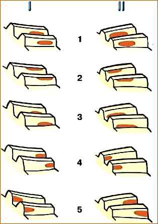
In Fig. Figure 11 shows typical positions of the contact pattern on the teeth of the driven gear and how to eliminate incorrect contact.
Move the drive gear by installing adjusting ring 5 (see Fig. 20) of a different thickness.
Move the driven gear by rearranging the gaskets of the 3 differential bearings.
Carry out the specified check of gear engagement on axles with final drives.
Assembling the rear axle
Assemble the rear axle after adjusting the gear engagement in the following order:
- 1. Install the gasket pack between the end of the front pinion bearing cap and the crankcase.
The thickness of the bag should be 1.3 times the gap (Fig. 12) between the ends of the cover and crankcase. If necessary, increase the thickness of the bag by 1.4 times.
- 2. Install the drive gear front bearing cover with collar assembly and secure with bolts.
- 3. Install the flange and washer. Tighten nut 7 (see Fig. 20) as far as possible so that the slots in it coincide with the holes in the gear shank and secure with a cotter pin. Tightening torque 167–206 Nm (17–21 kgf m).
Do not unscrew the nut to match the groove and the hole for the cotter pin.
- 4. Install the differential with driven gear and bearing assembly into the axle housing.
- 5. Install the gasket between the crankcase and the cover.
- 6. Install the crankcase cover so that both spring pads are at the top of the axle.
Connect the cover and crankcase using bolts and nuts.
- 7. While turning the drive gear, check for any binding or snagging in the assembled axle.
After assembling the bridge, check its heating while the car is moving. If the crankcase gets very hot (over 90 °C), check that the bearings are adjusted correctly.
")

")
")
")
")
")
")
")