Engine cooling system – liquid, closed, with forced circulation of coolant by a centrifugal pump
Coolant is supplied to the cooling jacket of the cylinder block.
Low-freezing liquid OZh-40 “Lena”, TOSOL-A40M or water are used as a coolant.
At ambient temperatures below minus 40 °C, coolant-65 “Lena”, TOSOL-A65M should be used.
For normal engine operation, the coolant temperature must be maintained within 70–90 °C.
This is done using a thermostat, which automatically regulates the amount of fluid passing through the radiator, and louvres, which regulate the amount of air cooling the radiator.
In cold weather, the cooling system must be protected with an insulating cover with a folding valve.
The coolant temperature is controlled by a temperature gauge located on the instrument panel and connected by an electrical wire to a temperature sensor screwed into the thermostat housing.
In addition, overheating of the coolant is indicated by a lamp with a red filter installed on the instrument panel and connected by an electrical wire to a temperature sensor screwed into the upper radiator tank.
The warning light lights up when the coolant reaches a temperature of 91–98 °C.
The causes of overheating may be: low fluid level in the radiator, weak fan belt tension, driving with the blinds closed and the insulating cover valve closed.
If the warning light comes on, the cause of overheating must be immediately identified and eliminated.
Pump 421.1307010–01 is a centrifugal type, driven by a V-belt from the crankshaft pulley.
The pump design uses a ball-roller bearing, manufactured integrally with the pump shaft.
The bearing has special seals that ensure preservation of the lubricant included during manufacture. The bearing does not require additional lubrication during operation.
Thermostat – with solid filling, placed in the housing.
Operating the engine without a thermostat is unacceptable, because when the thermostat is removed, the main fluid flow will circulate through a small circle of the cooling system, bypassing the radiator, which will lead to engine overheating.
When servicing the engine cooling system of model 414 and model 4178 (before 1999* production), it is necessary to take into account their design features: *
By the end of 1999, it is planned to completely switch to the production of model 4178 engines with coolant supplied to the cooling jacket of the cylinder block - coolant is supplied to the cylinder head;
– the pump (21–1307010–52) of the cooling system has two ball bearings installed. Lubricate the bearings according to the instructions in the lubrication table.
Lubricate the bearings through the grease nipple until the grease comes out of the inspection hole. Remove excess grease, as it may get on the fan belt and damage it;
– the coolant temperature control sensor is screwed into the cavity of the cooling system pump;
– the thermostat is installed in the outlet pipe.
Avoid getting coolant into the oil when removing the head or for other reasons, as this causes resinization of the oil, which can lead to coking and loss of mobility of the pushers, resin deposits and blocking of small holes supplying lubricant to the rubbing surfaces.
Maintenance of the cooling system consists of removing scale and sediment from it, adjusting the tension of the fan belt, and also flushing the radiator from the outside.
Every three years or every 60,000 km (whichever comes first), flush the cooling system and replace the coolant with new one.
Flush the cooling system as follows:
- – fill the system with clean water, start the engine, let it run until it warms up, with the engine idling, drain the water and turn off the engine;
- – after cooling the engine, repeat the above operation.
If there is significant deposit of scale and sediment, remove them from the cooling system by flushing with a strong stream of clean water.
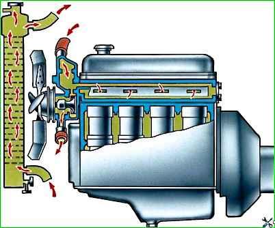
Wash the engine separately from the radiator (Fig. 1) so that rust, scale and sediment from the engine cooling jacket do not clog the radiator.
Before flushing the engine, in this case, remove the thermostat and disconnect the hoses from the radiator.
For better cleaning of the cooling jacket of the cylinder block, unscrew the drain cock along with the fitting from the cylinder block.
Rinse the cooling jacket until it comes out The water coming out of the engine will not be clean.
Do not use alkaline solutions to wash the cooling jacket, as they cause corrosion of the cylinder head and block.
Rinse the radiator with the cap closed, first supplying water to the upper pipe to remove sediment from the lower tank first, and then to the lower pipe.
Rinse until the water coming out of the upper tank is clear. At the same time, rinse the radiator core with a stream of water and blow with compressed air.
If there are significant scale deposits in the radiator tubes, do the following:
- 1. Remove the radiator from the car and fill it with a 10% solution of sodium hydroxide (caustic soda), preheated to a temperature of 90 ° C.
- 2. After 30 minutes, drain the solution from the radiator.
- 3. Rinse the radiator with hot water in the direction opposite to the coolant circulation in the engine (see Fig. 1) for 30–40 minutes under a pressure of no more than 49 kPa (0.5 kgf/cm2).
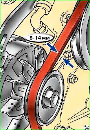
Adjust the fan belt tension by turning the generator.
The normal deflection of the belt should be 8–14 mm when pressed with a force of approximately 4 kgf (Fig. 2).
Check the operation of the thermostat simultaneously with flushing the cooling system, as well as in case of systematic overheating of the engine (if the power supply and ignition systems are working properly).
To check, place the thermostat together with a thermometer in a vessel with water heated to a temperature of 90–100 °C.
Then, as the water gradually cools, monitor the temperature of the beginning (80±2) °C and the end of closing (70±2) °C of the thermostat valve.
Replace the faulty thermostat with a new one.
When checking the thermostat, pay attention to the cleanliness of the valve disc. Remove scale and dirt from the surface of the thermostat with a wooden spatula, then rinse in water.
You can also check the serviceability of the thermostat by heating the inlet pipe of the upper radiator tank when the engine warms up.
If the thermostat is faulty, the pipe warms up immediately after starting the engine; if it is working properly, it will warm up after the water temperature in the block reaches 60–70 °C (according to the coolant temperature indicator on the instrument panel).
Check the blinds for complete opening with the drive handle pushed in all the way.
If the blinds do not open completely, then adjust them as follows:
- 1. Loosen the screw securing the drive rod in the articulated coupling of the lever located on the blinds.
- 2. Open the blinds completely by turning the drive lever counterclockwise.
- 3. Push the blind drive handle all the way in.
- 4. Secure the drive rod in this position in the articulated coupling of the lever.
- 5. Close and open the blinds several times in a row, then check the complete opening of the blinds with the handle pushed in all the way and their complete closure with the handle pulled out.
If the drive handle moves with great force, lubricate the axes of the blinds and the rod.
Lubricate the valve axes with engine oil, and the rod, after removing it from the shell, with Litol-24 lubricant.
The rod can be lubricated with an easily penetrating lubricant consisting of 60% colloidal graphite concentrate in mineral oil and 40% white spirit.
Apply lubricant to the rod shell.
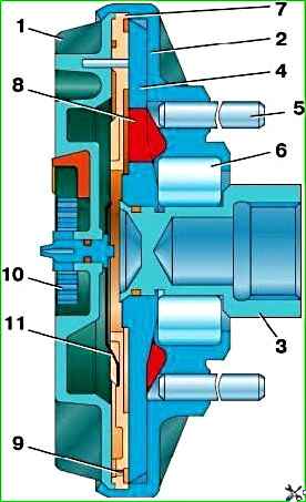
Model 4218 and 4178 engines can be equipped with a viscous fan drive coupling (Fig. 3), which reduces fuel consumption, reduces fan noise, and also helps warm up a cold engine and maintain engine thermal conditions within optimal limits.
The outer surface of the coupling should be kept clean to ensure the removal of heat generated during operation of the coupling and the normal operation of the bimetallic valve spring.
The clutch is turned on and off automatically.
If the clutch stops working, disconnect the clutch from the hub (the connection between the clutch and the hub has a left-hand thread), remove the fan, unscrew the two fan mounting studs from the clutch body, drain the working fluid through the holes in the studs and thoroughly rinse the inner cavity of the coupling with gasoline.
Allow the gasoline to drain completely, then pour it into the coupling through one of the holes 40g polymethylsiloxane liquid PMS-10000 TU 6-02-737-78.
The second hole must be open for air to escape.
After this, screw the studs into the housing, secure the fan and install the coupling on the hub of the cooling pump pulley.
Drain the liquid from the engine cooling system through two taps.
One of them is located on the lower radiator tank, the other on the cylinder block. When draining, remove the radiator cap.
")

")
")
")
")
")
")
")