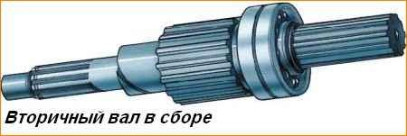
Disassembling a partially synchronized gearbox
Disassemble in the following order:
Remove the side cover with the switching mechanism.
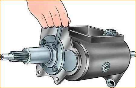
Remove the input shaft bearing cap
Rotate the input shaft with the cutout towards the intermediate shaft drive gear and remove the input shaft with rollers and synchronizer blocking ring.
Unscrew the locking screw of the reverse gear block axle and press the axle back, removing the reverse gear block
Remove the plates securing the rear secondary shaft bearing.
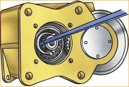
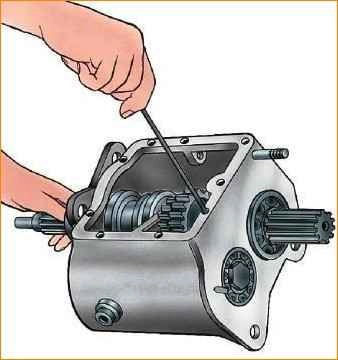
Remove the synchronizer hub retaining ring (Fig. 2) and remove the secondary shaft back.
In this case, all gears will be removed from the shaft, but the bearing will remain on the shaft.
Use a special wrench to unscrew the cover of the front bearing of the intermediate shaft.
Unscrew the nut of the front bearing of the intermediate shaft with a special wrench and remove the intermediate shaft together with the bearing back. In this case, the drive gears of “II” and “III” gears will be removed from the shaft.
Use a special wrench to unscrew the nut securing the input shaft bearing, which has a left-hand thread.
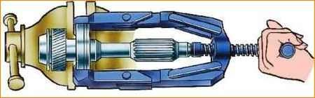
Remove the bearing from the input shaft using a puller
Remove the rear intermediate shaft bearing using a puller. The bearing mounting bolt has a left-hand thread and is secured with a disc spring.
Disassembling a synchronized gearbox
Disassemble in the following order:
- Remove the side cover with the switch mechanism.
- Using the M8 threaded hole in the rear end of the reverse idler gear axle, press the axle back and remove the gear.
- Remove the input shaft bearing cap.
- Remove the front intermediate shaft bearing cover.
- Unscrew the bolt securing the rear intermediate shaft bearing (the bolt has a left-hand thread) and remove the disc spring of the bolt.
- Using a puller, remove the rear bearings of the primary and secondary shafts by their retaining rings.
- Remove the rear intermediate shaft bearing retaining ring.
- Install the box so that the intermediate shaft is at the top, move the intermediate shaft forward until the intermediate shaft gear block stops in the crankcase.
- Feed the intermediate shaft together with the rear bearing back until the inner race of the front bearing comes out of the rollers and the rear bearing from the crankcase.
- Remove the rear intermediate shaft bearing using a puller.
- Install the gearbox with the hatch under the shift mechanism facing up.
- Remove the input shaft, the "IV" gear locking ring, the secondary shaft assembly (supporting the "I" gear spacer ring) and the intermediate shaft assembly from the transmission housing.
Disassembling the secondary shaft
- Remove the thrust washer and gear "I" with needle bearing.
- Remove the locking rings of the synchronizer hubs using a puller and a thrust washer.
- Remove the “I” and “II” gear synchronizer together with the “II” gear.
- Remove the retaining ring, key and bearing of the 2nd gear.
- Remove the synchronizer of “III” and “IV” gears together with the gear of “III” gear.
- Remove the circlip, key, spacer and bearing for the 3rd gear.
Assembling a synchronized gearbox
Assemble the gearbox, starting with the subassembly of its components, in the following order:
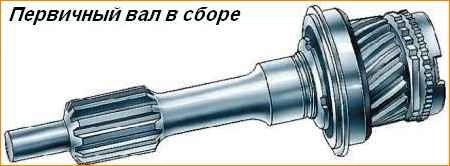
Assembling the input shaft
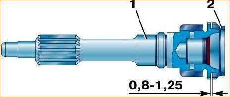
- Lap the blocking ring on the shaft cone to a size of 0.8–1.25 mm, as shown in Fig. With. 5
- Press the ball bearing with the sealing ring towards the bearing nut until it stops.
- Screw the bearing mounting nut (left-hand thread) and lock it by centering it in the groove of the shaft.
- Place grease into the shaft hole and insert the rollers (14 pieces).
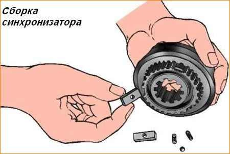
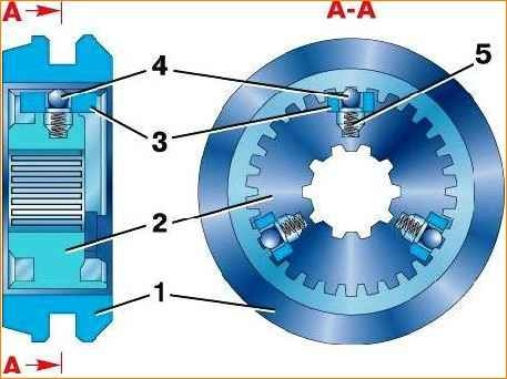
Assembling the synchronizer
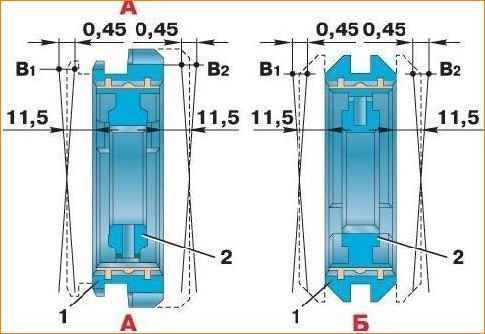
Select a set of couplings and synchronizer hubs with minimal clearances during free movement according to Fig. 6 or use factory-selected kits 469–1701117 and 469–1701138.
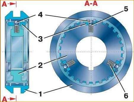
Insert three springs (Fig. 7), three guide springs, three balls and three crackers into the hub and install the clutch on the hub (the clutch for 1st and 2nd gears is made integral with the reverse gear).
Install the crackers with the side with the smaller diameter holes facing the coupling.
Assembling the secondary shaft
- Install the 3rd gear needle bearing, bearing spacer, snap ring and key.
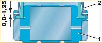
- Lap the synchronizer blocking ring on the third gear cone to a size of 0.8–1.25 mm, as shown in Fig. 8.
- Lubricate the bearing with transmission oil, install the 3rd gear with a locking ring, a thrust ring, install the 3rd and 4th gear synchronizer and the locking ring with the cut to the hub key.
- Lap the synchronizer blocking rings on the cones of the 1st and 2nd gears to a size of 0.8–1.25 mm, as shown in Fig. 8.
- Install the 2nd gear needle bearing and retaining ring.
- Lubricate the bearing with transmission oil, install the 2nd gear with a locking ring, thrust ring, install the 1st and 2nd gear synchronizer.
- Install the thrust ring, retaining ring, 1st gear with blocking ring and lubricated bearing, install the spacer ring (oil slinger) so that the pin of the secondary shaft fits into the groove of the spacer ring (oil slinger).
- Install the lock bushing and secure it (the lock bushing will make it easier to install the output shaft assembly into the transmission housing).
Reverse gear subassembly with bearing
Produced in a similar way to assembling a reverse gear with a partially synchronized gearbox bearing.
The assembly of gear shift mechanisms for vehicles of the UAZ-31512 and UAZ-3741 family is carried out similarly to the assembly of gear shift mechanisms for a partially synchronized gearbox.
Assembling a gearbox from assembled components
Further assembly of the gearbox is carried out in the following order:
- Insert the assembled (with gear assembly, retaining ring and inner roller bearing race) intermediate shaft into the transmission housing.
- Insert the assembled output shaft into the gearbox housing, remove the locking sleeve.
- Install (press in) the secondary shaft rear bearing with the retaining ring installed on it.
- When pressing the secondary shaft, place the mandrel against the end of the shaft journal under the synchronizer hub.
- When pressing, pay attention to the correct installation of the thrust washer of the 1st gear gear.
- Install (press) the assembled input shaft into the gearbox housing so that the groove for the bearing retaining ring is recessed into the housing.
- Install the intermediate shaft into place, engaging the gears.
- Install (press in) the rear bearing of the intermediate shaft with the retaining ring installed on it until the inner race of the bearing stops against the end of the shaft and the retaining ring against the end of the crankcase.
- Install the front bearing outer race with cage and rollers onto the front end of the intermediate shaft.
- Secure the rear intermediate shaft bearing with a bolt with a disc spring installed on it.
- Correct the primary shaft so that the groove for the locking ring comes out of the gearbox housing, install the locking ring and push the input shaft until the locking ring stops in the housing.
- Install (press in) the cover of the front bearing of the intermediate shaft until the ends of the cover and the crankcase coincide.
- Install the gasket on the front end of the crankcase so that the cutout in it coincides with the oil drain hole.
- Install the bearing cap on the input shaft so that the oil drain channel aligns with the cutout in the gasket.
- Secure the cover with four bolts and spring washers. Install the clutch release bearing release spring bracket under the two left bolts.
- Secure the output shaft rear bearing to the shaft using the thrust and circlips.
- Insert the reverse gear shaft into the housing hole from the rear mating plane.
- Insert the reverse gear into the crankcase so that the axle enters it from the side opposite the groove for the shift fork.
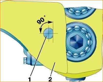
- Press the reverse gear axis into the crankcase as far as it will go according to Fig. 9.
Assembling a gearbox from assembled components
Carry out further assembly of the gearbox in the following order:
- Insert the assembled intermediate shaft into the gearbox housing.
- From the rear, place the spacer ring, the second gear, the third gear and the intermediate shaft drive gear in sequence.
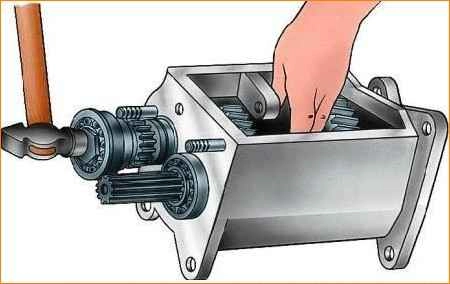
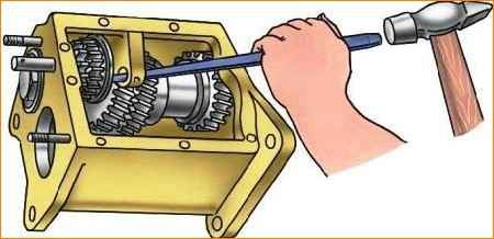
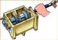
- Install the shaft (Fig. 10) with the bearing until the bearing race stops in the crankcase.
- Install the washer, bearing and tighten the special nut on the front end of the intermediate shaft. Open the nut to lock it. Axial movement of gears along the shaft is not allowed.
- Screw the cover with the rubber O-ring into the front hole of the crankcase flush with the end of the crankcase. Do not overtighten the cap to avoid damaging the O-ring.
- Lubricate the journals of the 2nd and 3rd gears of the assembled secondary shaft with liquid oil and, inserting it from behind into the upper hole of the crankcase, sequentially put on it the 1st gear, the 2nd gear, the 3rd gear with the synchronizer ring, the thrust washer, and the synchronizer assembly.
- Push the secondary shaft bearing together with the shaft up to the groove in the bearing.
- Secure the entire set of gears with a snap ring, installing it in the groove at the front end of the output shaft. Gears of 2nd and 3rd gears must turn freely by hand.
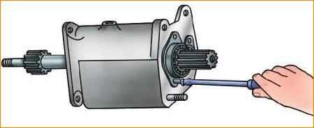
- Secure the rear bearing (Fig. 11) of the secondary shaft with two plates and screws.
- Install the blocking ring, ground to the input shaft cone, into the synchronizer hub.
- Insert the assembled input shaft into the transmission housing, with the cutout facing down toward the countershaft drive gear.
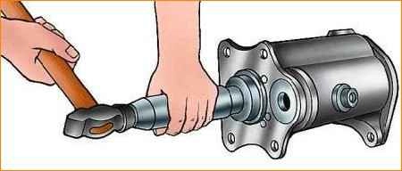
- Using a mandrel, install the shaft (Fig. 12) and the bearing until the bearing race stops in the crankcase.
- Install the gasket on the front end of the crankcase so that the cutout in it coincides with the oil drain hole.
- Install the bearing cap on the input shaft so that the oil channel of the cap coincides with the oil drain hole of the crankcase.
- Secure the bearing cap (Fig. 13) with four bolts and spring washers.
- Install the clutch release bearing release spring bracket under the two left bolts.
- Tighten the bolts with a torque of 12 to 18 Nm (1.2–1.8 kgf m).
- Lubricate the bearing of the reverse gear block with liquid lubricant, insert the gear block into with the largest crown to the crankcase hole and insert the axle into the block through the crankcase hole.
- Press the gear block axle into the crankcase so that the hole in the axle coincides with the M6 threaded hole in the crankcase wall.
Screw the locking screw flush with the plane of the crankcase connector (Fig. 14).
Install the shift mechanism on the gearbox and secure it with bolts and spring washers.
Before installing the shift mechanism, make sure that the gears in the transmission and the shift forks are in the neutral position.
Tighten the bolts with a torque of 12 to 18 Nm (1.2–1.8 kgf m).
Assembling a partially synchronized gearbox
Assemble the gearbox, starting with the subassembly of its components, in the following order:
Assembling the input shaft
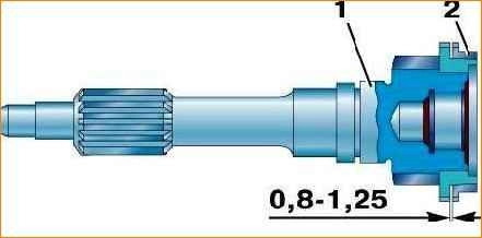
Lap the blocking ring on the shaft cone to a size of 0.8–1.25 mm, as shown in Fig. 15.
Install the oil deflector.
Press the ball bearing onto the shaft until it stops at the end of the oil deflector so that the groove on the outer ring of the bearing is shifted away from the ring gear.
Screw the bearing mounting nut (left-hand thread) and lock the nut by drilling it into the groove of the shaft.
Install the thrust ring onto the ball bearing.
Place lubricant into the shaft hole and insert the rollers (14 pieces).
Insert the roller retaining ring.
Assembling the secondary shaft
Install the oil deflector.
Press in the double row ball bearing with the markings facing the gearbox.
Secure the bearing to the shaft using a thrust washer and snap ring.
Assembling the intermediate shaft
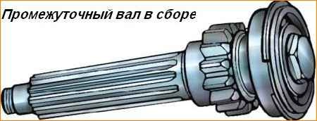
Press the bearing all the way onto the rear end of the intermediate shaft so that the groove on the outer ring of the bearing is shifted towards the gear.
Install the disc spring with its convex side toward the bolt head.
Tighten the bearing bolt (left-hand thread).
Install the thrust ring onto the bearing.
Assembling the third gear kit
Lap the synchronizer blocking ring on the third gear cone to a size of 0.8–1.25 mm, as shown in Fig. 16.
Subassembly of reverse gear block with bearing
Install the snap ring into one of the two grooves in the gear block hole.
Insert a thrust ring, a bearing and another thrust ring in sequence into the hole.
Install the retaining ring securely into the groove.
Assembling the synchronizer
Select a set of couplings and synchronizer hubs with minimal clearances during free movement according to or use kit 451D–1701116–11, selected by the manufacturer.
Put three springs (Fig. 19), three crackers, three balls into the hub and install the shift clutch on the hub.
Moreover, place the longer part of the hub towards the end of the coupling, which has a shaped chamfer (Fig. 20).
The holes in the crackers are made in steps.
Install the crackers on the side with the smaller diameter holes, and side of the coupling.
It is possible to install solid crackers with protruding hemispheres that act as balls in synchronizers.
Assembling the intermediate shaft cover
Install the rubber ring into the groove of the cover.
")

")
")
")
")
")
")
")