After disassembling, thoroughly rinse all gearbox parts in kerosene, blow with compressed air and inspect
Gearbox housing
External inspection will reveal cracks, chips, breaks in bosses and mounting lugs, the condition of the threads in the holes, the absence of nicks and burrs on the sealing surfaces.
Replace the crankcase with cracks, chips and kinks. Fix minor problems.
Gears. There should be no chips or nicks on the teeth.
The side surface of the teeth should not have any signs of chipping or crushing, and there should be no burrs on the end surfaces of the gears.
The seating surfaces must not have any damage or wear that could interfere with the alignment of the parts.
The gear rims of the synchronizers must not have damaged teeth or electric rivets.
The first gear gear of a partially synchronized gearbox must not have burrs extending beyond the height of the splines on the second gear engagement side.
Clean up any burrs.
The splines of this gear, mating with the seating surfaces of the secondary shaft, should not have metal deposits at the ends on the inner diameter side.
If they are available, during assembly, connect such a gear to the secondary shaft so that the fit is carried out through other splines that were not previously involved in the fit. Replace unusable parts.
The input shaft must not have any damage to the teeth of the fourth gear engagement ring.
There should be no chipping on the rolling surface of the roller bearing.
The shaft splines must not have nicks (the clutch driven disc must move freely along them).
Replace the worn shaft.
The secondary shaft should not have burrs or deep scratches on the seating surfaces under the gears of the first, second and third gears, chipped splines and chipping on the rolling surface of the roller bearing. Replace the worn shaft.
The intermediate shaft must not have any damage to the threads or teeth (crushing, chipping).
Replace worn shaft, shaft gear unit (on synchronized gearbox).
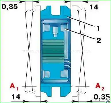
Note. When the parts move mutually by 14 mm, the misalignments in the splines, measured at points A1 and A2 on R40, should not exceed 0.35 mm (as shown)
Synchronizer
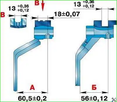
Check the connection of coupling 1 (see Fig. 13 and 37) of the synchronizer with hub 2 and if there are significant mutual movements exceeding twice those indicated in the figures in the direction perpendicular to the axis of the part, replace the coupling set with the hub
Select a new set according to the instructions in Fig. 13 and 37.
Replace the synchronizer clutch if the teeth are damaged or worn.
Replace the synchronizer blocking rings if the gap between the end of the ring and the end of the gear engagement ring is less than 0.3 mm, and also if the ring is deformed.
The bearings must not have damage to the cages, cracks and chips of the rings, chipping of the ball raceways, as well as noticeable radial and axial play.
Bearing cages must not be damaged. Replace worn bearings.
The side cover of the gearbox must not have chips, cracks, damage to the sealing surfaces and holes for installing plugs.
The rods must be straight and free of chipping in the area where the locks and clamps operate.
The locking pin of the third and fourth gear rod must move freely in the hole without falling out of it.
The length of the pin, taking into account wear, should not be less than 9.8 mm. Replace worn parts.
Forks must not be cracked or bent.

The position of the fork legs relative to the shift groove must correspond to the dimensions shown in Fig. 14 and 15.
If the wear of the shift grooves reaches 1 mm, replace the fork.
Other details
Gear thrust washers and keys must not be scored.
Oil deflectors must have the correct shape and not touch adjacent parts.
The disc spring of the intermediate shaft rear bearing bolt must not have cracks.
The rubber sealing ring of the front bearing cover of the intermediate shaft must not have ruptures or cracks.
The input shaft cover must not have cracks, kinks or damage to the working and seating surfaces.
The pins in the gearshift lever support should not swing in their sockets.
The rubber seal of the shift lever must not have ruptures or through cracks.
Replace all worn parts.