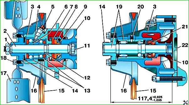
Possible malfunctions of the pump (Fig. 1) can be: fluid leakage through the impeller seal as a result of wear of the sealing washer or destruction of the rubber seal seal, wear of bearings, breaks and cracks of the impeller
Repair of pump 21–1307010–52 cooling system
Fix fluid leakage from the pump by replacing the sealing washer and rubber cuff.
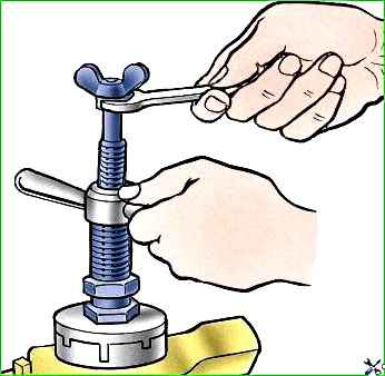
To replace, remove the pump from the engine, disconnect it from the bracket, remove the impeller using tool 71–1769 (Fig. 2), remove the sealing washer and oil seal seal.
To assemble the impeller seal, insert first the rubber seal assembly, then the sealing washer and retaining ring into the seal holder located on the pump body.
In this case, lubricate the part of the pump roller associated with the rubber cuff with soap before installing the oil seal and pressing on the impeller, and lubricate the end of the impeller in contact with the sealing washer with a thin layer of graphite lubricant.
Before installing the oil seal, check its end (the end of the sealing washer) for paint: when the oil seal is compressed to a height of 13 mm, the imprint of the end must have at least two completely closed circles without breaks.
Press the impeller onto the roller using a hand press until its hub touches the end of the flat.
In this case, the pump should rest with the front end of the roller on the table, and the force should be applied to the impeller hub.
To replace bearings or pump shaft, disassemble the pump completely in the following order:
Remove the impeller from the pump shaft and remove the sealing washer and rubber cuff.
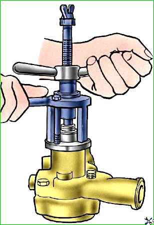
Unscrew the pulley hub mounting nut and remove it using the tool as shown in Fig. 3.
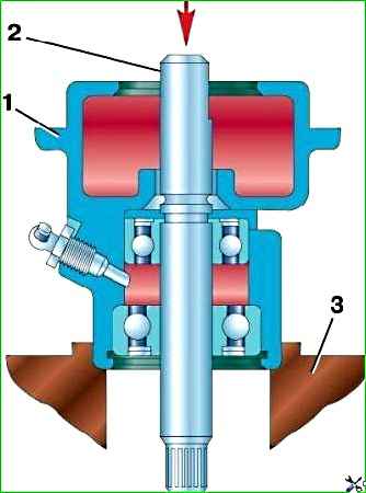
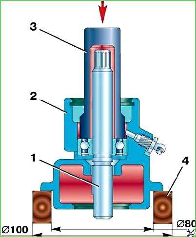
Remove the retaining ring of the bearings from housing 1 (Fig. 4) of the pump and use a press to press out or knock out roller 2 with bearings from the housing using a copper hammer, resting the front end of the housing on stand 3 with a hole for the passage of bearings.
Assemble the pump in the reverse order. In this case, press the new bearing onto the roller 1 (Fig. 5) and into the housing 2 simultaneously using a hand press and a mandrel
The felt seal of the bearing must face towards the retaining ring.
Putting the spacer sleeve on the shaft, press the second bearing with the felt gland facing outward.
After installing the retaining ring in place, press the pulley hub onto the front end of the shaft, resting the shaft against the rear end of the ring.
Press the pulley hub onto the pump shaft of the model 4218 engine after installing the clamp 19 (see Fig. 1, b).
When pressing the hub, do not allow any gap between the bearing and the retaining ring.
After assembling the pump, fill the housing cavity between the bearings with lubricant according to the instructions in the lubrication table.
When installing the assembled pump on the engine, pay attention to the suitability of the paronite gasket between the housing and the pump bracket.
Repair of pump 421–1307010–01 cooling system
Eliminate fluid leakage from the pump by replacing the oil seal 21 (see Fig. 1, b) assembled.
If the roller ball bearing 19 is worn, replace it as an assembly with the roller.
To replace the oil seal or roller assembly with bearing, remove the pump from the engine, disconnect it from the cover, and remove the impeller using tool 71–1769 (see Fig. 2).
Using the tool (see Fig. 3), remove the fan pulley hub and press out the roller and bearing.
Before pressing out the bearing, be sure to unscrew the lock 20 (see Fig. 1, b).
Press out the oil seal.
Assemble the pump in reverse order.
In this case, press the fan pulley hub all the way into the collar, and press the impeller to size 117.4 +0.925 –1.035 (see Fig. 1, b ).
Before assembly, lubricate the part of the roller ball bearing associated with the oil seal with soap, and the end of the impeller in contact with the oil seal with graphite lubricant.
When installing the assembled pump on the engine, pay attention to the suitability of the paronite gasket between the cover and the pump housing.