Disassembling the switching mechanism of cars of the UAZ-31512 family:
Disassemble in the following order:
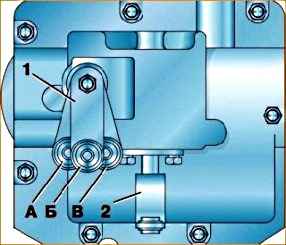
- 1. Unscrew the four screws of the shift lever support and remove the support with the lever and the preload spring (this operation is done before removing the entire unit from the car).
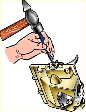
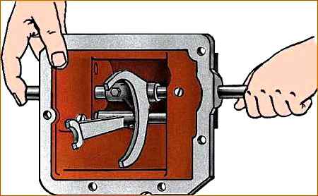
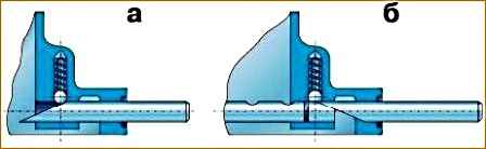
- 2. Remove the three rod hole plugs on one side of the cover (Fig. 2).
- 3. Unscrew the plug of the rod clamp socket for 1st and 2nd gears and remove the spring and ball.
- 4. Undo the pins and remove the fork locking screws.
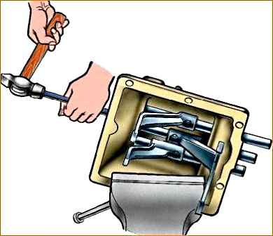
- 5. Press out the rods (Fig. 3) of the shift forks through the holes in the cover where the plugs are removed, and remove the forks.
- When pressing out the rods of the 3rd and 4th gears and reverse gear, do not lose the retainer ball ejected by the spring.
- 6. Remove the springs and rod retainer balls.
- 7. Remove the two lock plungers through the hole in the 1st and 2nd gear lock.
- 8. Unscrew the three screws and remove the fuse cover and return spring.
- 9. Slide the fuse plunger out, remove the retaining ring and remove the plunger. At the same time, hold the plunger lock ball from falling out.
- 10. Remove the spring and retainer ball.
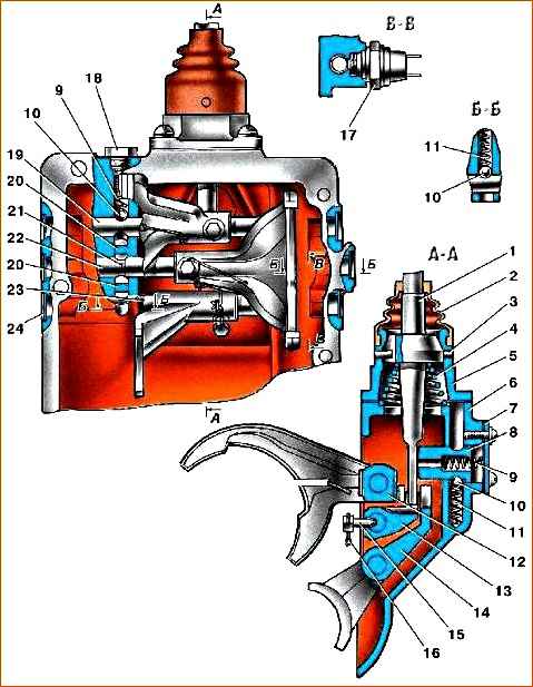
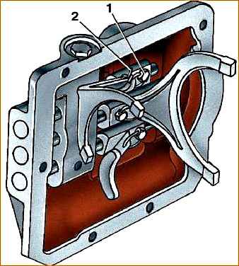
1 - reverse fork rod; 2 - reverse fork; 3 - fork rod for 3rd and 4th gears; 4 - fork of III and IV gears; 5 - fork of 1st and 2nd gears; 6 - fork rod for 1st and 2nd gears; 7 - cotter pin; 8 - plug; 9 - washer; 10 - gear shift shaft; 11 - side cover; 12 - gear shift clutch; 13 - blocking spring; 14 - gasket; 15 - oil seal cover; 16 - shift lever; 17 - plug; 18, 20 - clamp springs; 19 - lock plunger; 21 - locking ball; 22 - gear selection lever; 23 - selective lever; 24 - pin; 25 - reverse light switch; 26 - cap
Disassembling the switching mechanism of cars of the UAZ-3741 family
Disassemble in the following order:
- 1. Remove the three plugs for the rod holes in one of the ends of the cover (see Fig. 2).
- 2. Undo the cotter pins and remove the fork locking screws.
- 3. Unscrew the plug of the rod lock socket for 1st and 2nd gears and remove the spring and lock ball.
- 4. Press the rods (see Fig. 3) through the holes in the cover where the plugs are removed and remove the forks. When pressing out the rods of III and GU gears and reverse gear, do not lose the retainer ball ejected by the spring.
- 5. Remove the springs and balls of the rod clamps; remove the two lock plungers through the hole in the 1st and 2nd gear lock.
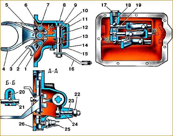
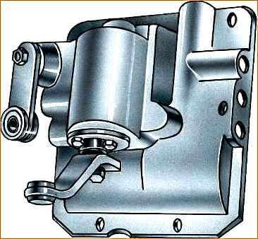
- 6. Unscrew the nut and remove lever 22 from the splines (see Fig. 4),
- 7. Knock down the pin 24 securing the lever axis 23 and remove the axis together with the selection lever.
- 8. Unscrew the nut and remove lever 16.
- 9. Unscrew the three bolts, remove the oil seal cover 15 and remove the spring. Having lowered shaft 10 with coupling 12 and two washers, remove the shaft through the side cavity of the cover.
Before removing levers 22 and 16, note the relative position of the levers on the rollers in order to return the levers to their previous position.
Disassembling the gear shift control mechanism for cars of the UAZ-3741 family
perform assembly in the following order:
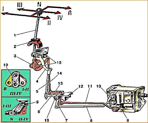
1 - gear shift lever; 2 - mechanism seal; 3 - selecting lever of the mechanism; 4 - switching lever of the mechanism; 5 - vertical shift rod; 6 - intermediate shift lever; 7 - intermediate selection lever; 8 - horizontal selection rod; 9 - gear shift lever; 10 - gear selection lever; 11 - horizontal shift rod; 12 - intermediate bracket for arms; 13 - intermediate selection lever; 14 - vertical selection rod; 15 - grease nipples
- 1. Disconnect rods 8 and 11 (Fig. 5) from levers 9 and 10.
- 2. Unscrew rods 5 and 14 from levers 6 and 13.
- 3. Disconnect the bracket 12 intermediate arms.
- 4. Remove the mechanism bracket together with gear shift lever 1.
- 5. Wash the control mechanism parts.
- 6. By external inspection, identify wear in the levers and rods.
- 7. Replace worn parts.
Assembling the gear shift control mechanism for cars of the UAZ-3741 family
Assemble the mechanism in the reverse order of disassembly. After assembly, adjust the gearbox control mechanism.
Adjustments are made by changing the length of the horizontal rods – 8.11 (see Fig. 5) and vertical rods – 5.14 in the following order:
- 1. Before starting the adjustment, set lever 9 to the neutral position (N), and lever 10 to position III–IV until it stops against the locking spring.
- 2. Place gear shift lever 1 in the position corresponding to the selection of gears I and II. In this position, connect and secure selection rods 8 and 14, preventing the levers from being pulled up.
- 3. After this, place lever I in the position corresponding to the selection of gears III and IV and also freely connect shift rods 5 and 11.
- 4. After completing the adjustment, check that the gears are fully engaged. To do this, engage first gear and make sure that the rods and levers do not rest against adjacent parts.
Perform the same check by engaging reverse. At the same time, make sure that the intermediate lever 6 does not rest against the frame cross member and the mudguard.
When reverse gear is engaged, the gap between them should be 2–3 mm.
Assembling the gear shift mechanism for cars of the UAZ-3741 family
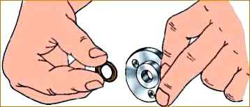
- 1. Install the rubber o-ring (Fig. 6) into the shift shaft oil seal cover.
- 2. Install the rubber sealing ring into the hole under the axis of the selective lever 23 (see Fig. 6).
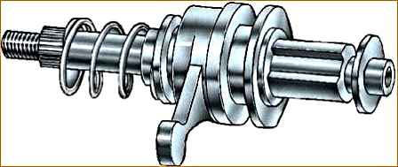
3. Install the clutch (Fig. 7), thrust washer, spring thrust cup and spring onto the shift shaft.
Insert the shaft into the side cover housing and install the oil seal cover with the gasket, secure the cover with three bolts.
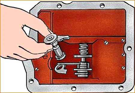
4. Install the selector lever assembly with the axle (Fig. 8) into the cover body so that the lever fits into the groove of the shift clutch.
Secure the lever with a pin, which you hammer in from below.
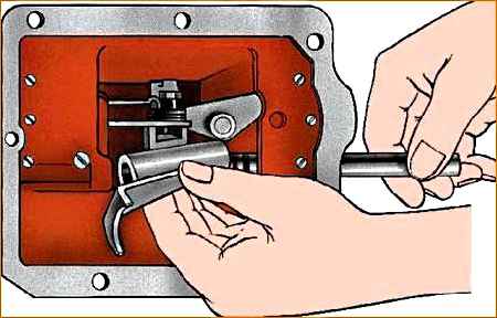
5. Turn the side cover over with the machined flange up and insert the springs and balls of the third and fourth gear rod and the reverse rod into the sockets of the retainers using a mandrel (see Fig. 9).
6. Install the reverse fork on the rod on the side opposite to the lock, and, pushing the ball of the lock (Fig. 10) into the cover body from to using the power of the mandrel (see Fig. 10), set the rod to the neutral position.
Assemble all the rods (Fig. 10) and forks in sequence.
Install locking blocks between the rods.
- 7. Secure the forks to the rods with conical bolts and pin them with wire (Fig. 11), which should not interfere with the movement of the forks.
When attaching the forks, the shift clutch lever must be in the groove of the forks.
- 8. Insert the ball and the retainer spring into the hole in the rod of the 1st and 2nd gears and tighten the plug. Please keep in mind that the rod clamp spring for 1st and 2nd gears in the free state is longer than the other two rod clamp springs.
- 9. Install six plugs into the end holes of the cover body, a plug into the hole for the shift shaft and hammer them out.
- 10. Install the selection and shift levers (Fig. 12) onto the shaft splines and secure them with nuts and spring washers.
The correct position of the levers is checked with the gears in the neutral position in the gearbox after installing the shift mechanism on the gearbox in accordance with Fig. 13.
Assembling the gear shift mechanism for cars of the UAZ-31512 family
Assemble the gear shift mechanism in the following order:
- 1. Install the spring and fuse retainer ball into the socket.
- 2. Compressing the retainer spring, insert the fuse plunger into the hole from the inside of the cover until it stops.
- 3. Install the retaining ring on the plunger.
- 4. Insert the return spring into the plunger body.
- 5. Close the fuse plunger with the cover and gasket and tighten the three screws with spring washers.
- 6. Turn the cover over with the large flange up and place springs and balls for the 3rd and 4th gear rods and the reverse rod into the sockets of the clamps.
- 7. Insert the reverse fork rod into the cover on the side opposite the lock, install the fork on the rod and, recessing the ball using a mandrel (Fig. 14), install the rod on the neutral position lock; In the same way, assemble all the rods and forks in sequence, starting with the reverse rod. Place locking pins between the rods.
- 8. Secure the forks to the rods with conical bolts and cotter the bolts with wire.
The cotter wire should not interfere with the movement of the forks.
- 9. Place a ball and a spring into the hole in the rod clamp for 1st and 2nd gears and screw in the plug. Keep in mind that the 1st and 2nd gear rod retainer springs, when free, are longer than the other two rod retainer springs.
- 10. Insert six plugs into the end holes of the housing for the rods and tap out the plugs.
- 11. Lubricate the shift lever support sphere assembled with the trunnions and place the sphere on the shift lever.
- 12. Place the gasket on the shift mechanism cover and install the conical spring in the annular recess.
- 13. Install the support along with the lever on the cover so that the lever enters the spring, and the support closes the hole in the body with its tide and secure the support with four screws and spring washers.
- 14. Place the rubber seal on the lever and support and screw on the handle.
")

")
")
")
")
")
")
")