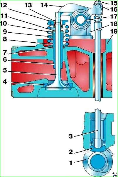
The valves are driven from the camshaft through pushers, pushrods and rocker arms (Fig. 1)
The camshaft is forged steel, has five bearing journals, valve drive cams, an oil pump drive gear and an eccentric for the fuel pump drive.
The shaft support journals in the cylinder block on sliding bearings are steel bushings filled with an antifriction alloy (on engines model 4178 from December 1995 and model 4218, bushings are not installed).
The camshaft is driven from the crankshaft by a pair of gears with helical teeth. The gear on the crankshaft is cast iron, and on the camshaft there is a plastic ring with a cast iron hub.
Both gears have two threaded holes for a puller.
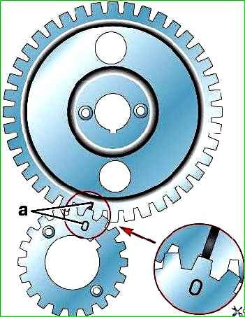
The correctness of the distribution phases is ensured by installing the gears according to the marks (Fig. 2).
The “O” mark on the crankshaft gear should be against the groove of the tooth on the camshaft gear.
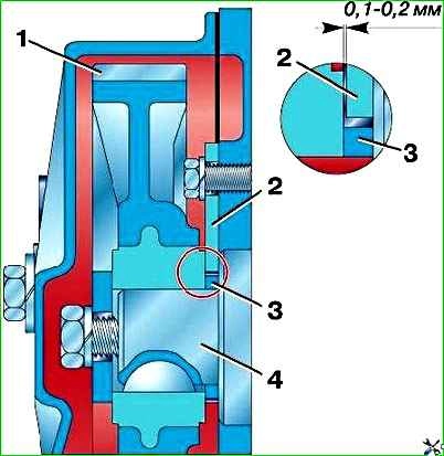
Axial movement of the camshaft is limited by steel thrust flange 2 (Fig. 3), located between the end of the camshaft journal and the gear hub.
A working gap of 0.1–0.2 mm between the gear hub and the thrust flange is ensured by the fact that the spacer ring 3, sandwiched between the gear and the camshaft journal, is thicker than the thrust flange.