Maintenance of the K-126GU carburetor (for engines mod. 4178)
The K-126GU carburetor is used to complete the 4178 model engines, as an option to replace the K-151V carburetor
Nominal flow rate of carburetor jets K-151V, K-151E, K-151U, (ml/min)
Carburetor maintenance consists of periodically checking the reliability of fastening of the carburetor and its individual elements, checking and adjusting the fuel level in the float chamber, adjusting the low speed of the engine crankshaft in idle mode, checking the operation of the accelerator pump and economizer, cleaning, purging and flushing carburetor parts from tarry deposits, checking the flow rate of the jets.
Check the fuel level with the car engine not running and installed on a horizontal platform.
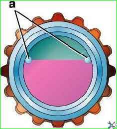
When pumping fuel using a manual pump drive, the fuel level in the carburetor float chamber must be established within the limits marked by the marks (tides) “a” (Fig. 2) on the walls of the inspection window.
If the level deviates from the specified limits, make an adjustment by removing the float chamber cover.
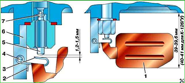
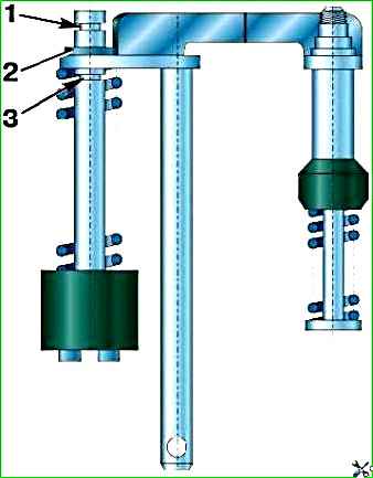
Adjust the level by bending tongue 3 (Fig. 3).
At the same time, by bending limiter 2, set the needle stroke 5 of the fuel supply valve to 1.2–1.5 mm.
After adjustment, check the fuel level again and, if necessary, adjust again.
Considering that during operation due to wear of the float mechanism the fuel level gradually increases, set it when adjusting to the lower limit.
In this case, the fuel level will remain within acceptable limits for a longer period of time.
When adjusting the fuel level in the carburetor float chamber, do not bend the float tongue by pressing the float, but bend it using a screwdriver or pliers.
Adjust the low crankshaft rotation speed in idle mode on a warm engine with a working ignition system.
Make adjustments in the following order:
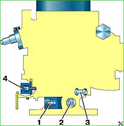
Preliminarily set the crankshaft rotation speed at idle speed with screw 2 (Fig. 4) to 550–600 min -1 .
Set screw 1 to the position that provides the highest engine speed at a given throttle position.
Screw 1 also regulates the CO content in the exhaust gases.
Finally set screw 2 to low idle speed (550–650 min -1).
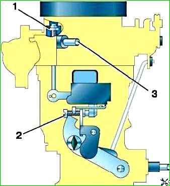
Adjust valve drive 1 (Fig. 5) for unbalancing the float chamber with screw 3.
When the throttle valve is fully released, the valve should be open.
Check the operation of the accelerator pump if, when you press the throttle pedal sharply, there are dips in engine operation and the engine slowly increases speed.
To check, sharply open the throttle valve, while fuel should flow from the accelerator pump nozzle Ivo.
On a special stand you can check the flow of the accelerator pump, which should be at least 8 cm 3 per 10 working strokes of the piston.
During the operation of the carburetor, due to wear of the piston and the walls of the accelerator pump well, its supply may be insufficient.
To increase the flow, move limit washer 2 (Fig. 6) on the accelerator pump rod to the lower groove 3.
When operating a vehicle in high-temperature conditions, reduce the flow of the accelerator pump by moving the limit washer to the upper groove of rod 1.
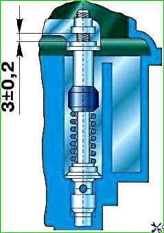
If the engine does not produce maximum power at full throttle, check that the economizer is fully engaged.
To do this, check the gap between the bar and the nut of the economizer drive rod with the throttle valve fully open, which should be (3±0.2) mm (Fig. 7).
If necessary, adjust this gap using a nut, then secure the nut by crimping it along its small diameter.
Table 1
Main fuel jet:
- First camera - 225;
- Second camera 330 (330/380)
Main air jet:
- First camera - 330;
- Second chamber - 230 (230/330)
Idle jet block:
- idle pipe 95(110/95)
- emulsion tube 85
- Idle air jet 330 (175/330)
- Emulsion jet idle 280 (175/210)
- Fuel jet of transition system 150 (200/150)
- Air jet of transition system 270
Some jets of carburetors K-151V, K-151E and K-151U have different flow capacities.
In parentheses it is indicated: in the numerator - for K-151E, in the denominator - for K-151U.
In principle, the K-126GU carburetor is similar to the K-151V carburetor, but has a simpler design (there is no autonomous idle system, an EPH system and a float chamber ventilation valve).
Carburetor maintenance is similar to maintenance of the K-131 carburetor.
Adjustment of the minimum idle speed of the crankshaft is carried out in the following sequence:
– tighten the screw that changes the composition of the mixture all the way, but not tightly, and then unscrew it 1.5 turns;
– start the engine and use the throttle valve thrust screw to set a stable crankshaft speed of 550–650 min -1 .
The emission limiter screw adjusts the limit value of carbon monoxide.