Remove and disassemble the main brake cylinder in the following order:
Disconnect the lines leading from the master cylinder to the warning device.
Disconnect the warning device from the brake master cylinder.
Disconnect the brake master cylinder from the vacuum booster.
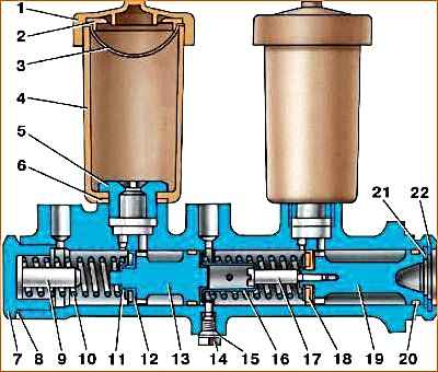
Unscrew the thrust bolt 14 (see Fig. 1).
Remove the lock ring 22 and take out the thrust washer 21.
Remove the primary chamber piston assembly 19.
Unscrew plug 7, remove plug insert 9, return spring 10 and secondary chamber piston assembly 13.
Tanks 4 are not recommended to be removed unless necessary. If necessary, to remove them, unscrew the plugs of the tanks 1, remove the screens 3 and unscrew the fittings 5 securing the tank bodies.
Pull out piston assembly 19 only towards the flange, and remove piston assembly 13 towards the opposite end.
Remove the pistons carefully so as not to damage the sealing collars 18 and rings 20.
If the pistons cannot be removed freely from the cylinder, first lightly push piston 13 with piston 19, and then carefully push piston 19 by pressing (through the vacated cavity) with a screwdriver or other object onto spring holder 16 or spring holder screw 17.
Assemble and install the master cylinder in the reverse order.
In this case, install the assembled pistons into the cylinder carefully and only from the side of the corresponding ends of the cylinder.
To avoid damaging the seals and rings, do not push the pistons through the entire cylinder cavity.
When assembling piston 19, screw screw 17 until it stops in the piston.
Wrap the thrust bolt 14 into the crankcase only after installing the assembled piston 19, washer 21 and retaining ring 22.
Tightening torques:
- - thrust bolt 14 - 8–10 Nm (0.8–1.0 kgf m);
- - fitting 5 - 16–22 Nm (1.6–2.2 kgf m);
- - plugs 7 - 167–186 Nm (17–19 kgf m).
")

")
")
")
")
")
")
")