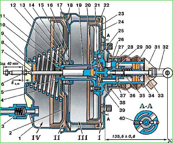
If the amplifier fails, only the force from the driver’s foot is transmitted to the pistons of the master cylinder through pusher 33 (see Fig. 1), control valve, buffer 20 and rod 7
An increased pedal force indicates the need for inspection and possibly repair of the amplifier.
If seals, springs and other parts fail, remove the amplifier from the car by first disconnecting the brake master cylinder, hose, pedal and disassemble it.
Before disassembling, mark the body and cover so that they can be installed in their original places during reassembly.
Disassemble and reassemble the amplifier in a special device using a small press.
Install the amplifier with four bolts, with rubber bushings put on them to protect the threads from damage in the holes of the stationary plate.
On the two bolts of the secondary chamber cover, having also previously secured their threads, install a special lever with holes for these bolts and, pressing it with a little force with a press, turn the cover until the protrusions on the amplifier body align with the depressions on the cover.</p >
Other operations do not require special devices.
When assembling, lubricate the working friction surfaces of parts 6,17, 24, 25 and the contacting surfaces of cover 1 with diaphragm 18 with Tsiatim-221 lubricant.
After assembly, check the amplifier for functionality and tightness.
To do this, attach the hose to the check valve and, with the engine running, apply a force of 196–294 N (20–30 kgf) to pusher 33.
In this case, the control valve body together with the pusher must move all the way.
After removing the force from pusher 33, the control valve body should return to its original position.
After 2-3 minutes after stopping the engine, when you press pusher 33, you should hear the hiss of air entering the amplifier through the control valve.
Before installing the master brake cylinder on the booster, adjust the extension of the rod 7 relative to the mating plane of the cover 1 to 7.78–8 mm and the extension of the pusher 33 relative to the mating plane of the body 23 to 134.7–136.3 mm.
")

")
")
")
")
")
")
")