Assemble the transfer case from a subassembly of its components
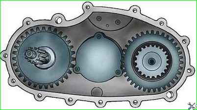
Crankcase assembly
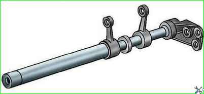
Press the thrust cup of the drive shaft bearing into the crankcase until it stops (if it was removed).
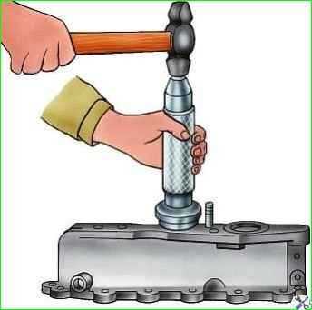
Press the roller bearing into the crankcase (Fig. 1), maintaining a size of 6–0.5 mm from the end of the crankcase.
Screw in the oil drain and oil filler plugs.
Insert and tap out the intermediate shaft bearing plug.
Assembling covers
Press the cuff into the cover until it stops.
Fill the cavity between the working edges of the cuff with Litol-24 lubricant.
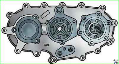
Assembling the rear axle drive shaft
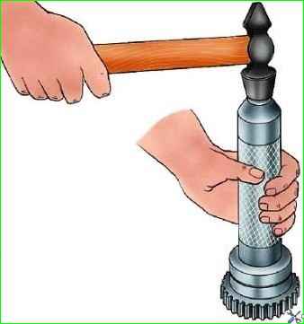
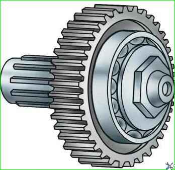
Press the bearing onto the shaft until it stops (Fig. 2).
Assembling the intermediate shaft
Press the roller bearing ring onto the shaft (if it is provided for in the design).
Select the front axle gear according to the shaft splines with minimal clearance when it moves freely along the shaft.
Press the bearing onto the rear end of the shaft so that the groove for the thrust ring is offset outward.
Install the retaining ring.
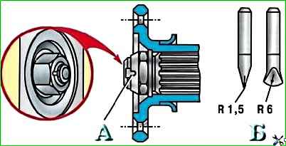
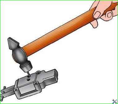
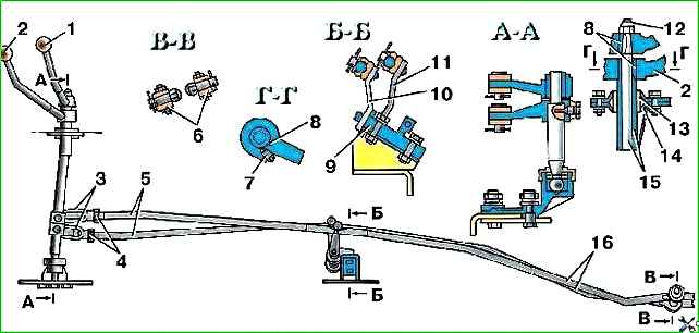
On an old-style box, tighten the shaft fastening nut as far as possible and lock it by bending the edge into the groove of the shaft.
For bending, use only tools with rounded edges (see Fig. 3).
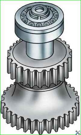
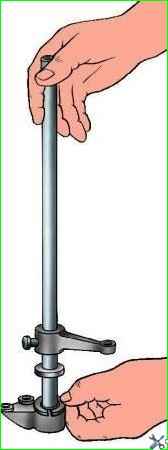
The intermediate shaft assembly is shown in Fig. 4.
Assembling the front axle drive shaft
Press the bearing onto the shaft from the gear side so that the groove for the retaining ring is offset towards the nut.
- Tighten the nut and lock it by bending the edge into the groove of the shaft (see Fig. 2).
- For bending, use only tools with rounded edges.
- The front axle drive shaft assembly is shown in Fig. 5.
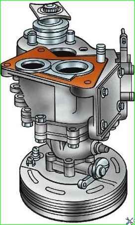
Assembling the transfer case shift mechanism cover
The switching mechanism (disassembled) is shown in Fig. 6.
- Place rubber rings into the holes in the cap for the rods.
- Insert the forward and downshift selector rod into the cover (it has an oblong flat), while putting the lever with a short hub on it.
- Insert a retaining ball with a diameter of 11 mm into the lid through the side hole.
- Insert the front axle engagement rod into the cover (it has a semicircular groove), while simultaneously putting the lever with a long hub on it.
- Insert the pins (Fig. 7) through the top holes in the cover and drive them flush, securing the levers to the rods.
- External pins on rods place them in different directions, and place the levers with their planes facing each other.
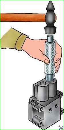
Insert and hammer out the plugs with a mandrel (Fig. 8).
- * Install the stamped bracket of 5 (see Fig. 15) levers on the cover and secure it with three bolts and spring washers.
- * Lubricate the lever axle with Litol-24 grease and insert it into the bracket, putting on the axle in sequence a polyethylene washer, a forward and downshift lever, two flat springs, a front axle shift lever and a polyethylene washer.
In this case, the forks of the lower ends of the levers should engage with the pins of the rods, and the flat springs should grip the rods of the levers.
- * Install the spring washer on the axle and tighten the nut until it stops.
- * Screw the grease nipple into the axle so that its spout is turned toward the plane of the cover connector.
- * Screw the handles onto the levers.
- * For vehicles of the UAZ-31512 family
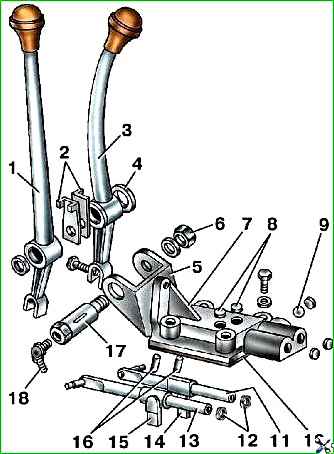
Assembly of control shafts for vehicles of the UAZ-3741 family
The transfer case control mechanism is shown in Fig. 9.
- Install the rubber cuff on the spherical end of the front axle engagement shaft, lubricate the sphere with graphite grease and install two cotters.
- Place graphite grease into the shaft support and insert the shaft with nuts into the bracket socket.
Secure the crackers (Fig. 10) with a spring lock ring and close with a rubber cuff.
Install a polyethylene washer (Fig. 11) and a tubular rear axle engagement shaft onto the control shaft
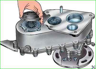
Assembling a transfer case from subassembled units
Further assembly of the transfer case is carried out in the following order:
- Insert the assembled front axle drive shaft into the lower hole of the crankcase cover, place the thrust ring in the bearing groove and install the shaft until it stops (Fig. 12).
- Insert the assembled shaft (Fig. 13) of the rear axle drive into the upper hole of the crankcase cover.
- Lubricate the teeth of the speedometer drive gear with transmission oil, put the gear on the rear axle drive shaft, put the oil deflector on the shaft and press the bearing with the thrust ring until it stops.
- Insert the assembled intermediate shaft into the middle hole of the crankcase cover, put the thrust ring on the bearing and install the shaft until it stops (Fig. 14).
- Install the bearing caps and secure them with bolts and spring washers.
- Install the parking brake on the rear axle drive shaft bearing cover.
- Place a flange and washer onto the splines of the rear axle drive shaft, tighten the nut as far as possible and lock it by bending the edge into the groove of the shaft using a center punch, as shown in rice. 3.
- Insert the rod, which has two grooves, into the hole in the crankcase cover so that the copper-plated end of the rod is on the outside.
- Insert the front axle shift fork (wide and short) into the groove of the front and rear axle shift gear. Insert the spring and the retaining ball into the fork socket.
- Insert the rod into the fork, compressing the retainer spring.
- Press the copper-plated end of the rod into the crankcase cover up to the groove.
- Place the forward and downshift fork onto the rod with three grooves.
- Press the rod with the copper-plated end into the crankcase cover up to the groove.
- Insert the locking plate into the grooves of the rods and secure it with a bolt and spring washer.
- Insert the forward and downshift gear into the fork and turn it (together with the fork) into the direct gear position.
- Install the gears and shafts assembled on the cover into the crankcase, connect the crankcase to the cover and tighten the bolts with spring washers.
- Press the bearing onto the front axle drive shaft, install the gasket, close the bearing with a cover with a cuff (Fig. 15).
- Secure the cover with bolts and spring washers.
- Place a flange and washer onto the splines of the front axle drive shaft, tighten the nut as far as possible and lock it by bending the edge of the nut into the groove of the shaft.
- Lubricate the journal and teeth of the speedometer driven gear with transmission oil.
- Place the fitting onto the gear and insert it into the hole in the transfer case cover.
- Secure the fitting with a locking plate and a bolt with a spring washer.
- Install the shift mechanism cover gasket onto the crankcase connector, install the cover with levers and rods so that the levers fit into the grooves of the corresponding forks, and secure it with bolts and spring washers.
- Install the gasket on the connector of the power take-off hatch, close the connector with the cover and secure the cover with bolts and spring washers.
- Install the cover with the convex side of the embossed polygon facing outwards.
Assembling the transfer case with gearbox
Assemble the transfer case with the gearbox in the following order:
- Turn on “II” gear in the gearbox.
- Insert the transfer case drive gear into engagement with the rear axle drive shaft.
- Install the transfer case onto the parking brake drum with the flange facing up.
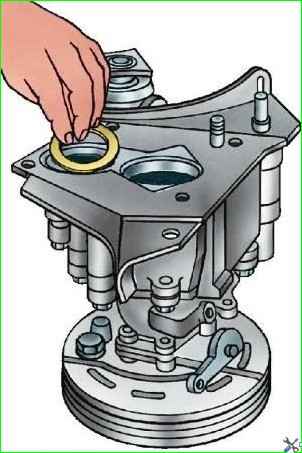
- Install the sealing gasket on the transfer case (Fig. 16).
- Install the suspension plate (Fig. 17) on the transfer case and press it against the gasket.
- Install the thrust ring of the gearbox intermediate shaft bearing into the transfer case socket.
- Put a gasket on the plate.
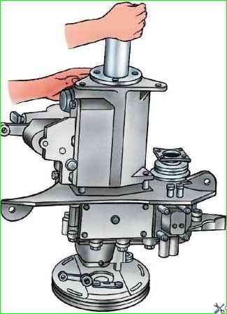
- Install the gearbox (Fig. 18) onto the transfer case so that the holes for the studs and bolts line up.
- While turning the gearbox input shaft, align the splines of the gearbox secondary shaft with the splines of the transfer case drive gear and push the gearbox down.
- Install spring washers under the nuts and bolt heads and, evenly tightening the nuts and bolts, connect the gearbox to the transfer case.
Check the engagement of all gears in the transfer case by turning the shafts by hand by the brake drum or the flange of the front axle drive shaft and by the input shaft of the gearbox.
All gears must be clearly secured with clamps in the engagement and neutral positions.
The downshift should only be engaged after the front axle is engaged.
")

")
")
")
")
")
")
")