If the oil pump parts wear out a lot, the pressure in the lubrication system decreases and noise appears
When disassembling the pump, check the elasticity of the pressure reducing valve spring.
The elasticity of the spring is considered sufficient if a force of (54±2.45) N [(5.5±0.25) kgf] is necessary to compress it to 24 mm in height.
Oil pump repair usually involves grinding the ends of the covers, replacing gears and gaskets.
When disassembling the pump, pre-drill the riveted head of the bushing mounting pin 2 (see Fig. 1) on its shaft 1, knock out the pin, remove the bushing and pump cover.
After this, remove the pump shaft together with the drive gear from the housing towards its cover.
In case of disassembling the drive gear and shaft, drill out the pin with a drill with a diameter of 3 mm.
Replace the drive and driven gears with chipped teeth, as well as with noticeable wear on the surface of the teeth with new ones.
The drive and driven gears installed in the pump housing should be easily rotated by hand using the drive shaft.
If there is significant (more than 0.05 mm) wear on the inner surface of the cover from the ends of the gears, grind it.
Paronite gaskets with a thickness of 0.3-0.4 mm are installed between the cover, plate and pump housing.
The use of shellac, paint or other sealing substances when installing the gasket, as well as installing a thicker gasket, is not allowed, as this causes a decrease in pump flow.
Assemble the pump taking into account the following:
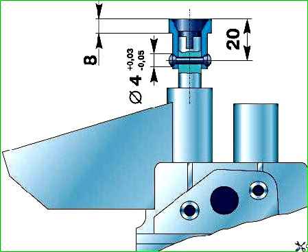
- 1. Press the bushing onto the drive roller, keeping the size between the end of the drive roller and the end of the bushing to 8 mm (Fig. 2). In this case, the gap between the pump housing and the other end of the bushing must be at least 0.5 mm.
- 2. Drill a hole with a diameter of 4 +0.03–0.05 mm in the drive roller and in the bushing, maintaining a size of (20 ± 0.25) mm.
- 3. Countersink the hole on both sides to a depth of 0.5 mm at an angle of 90°, press a pin with a diameter of 4-0.048 mm and a length of 19 mm into it and rivet it on both sides.
If the pump’s performance cannot be restored by repair, then replace it with a new one.
Install the oil pump drive and ignition distributor onto the block in the following order:
- 1. Remove the spark plug of the first cylinder.
- 2. Install a compression gauge in the spark plug hole and turn the crankshaft with the starting handle until the arrow begins to move. This will happen at the beginning of the compression stroke in the first cylinder.
You can plug the hole for the candle with a paper wad or your thumb. In this case, during the compression stroke, the wad will pop out or air will be felt escaping from under the finger.
- 3. After making sure that compression has begun, carefully rotate the crankshaft until the hole on the crankshaft pulley rim aligns with the pointer (pin) on the camshaft cover.
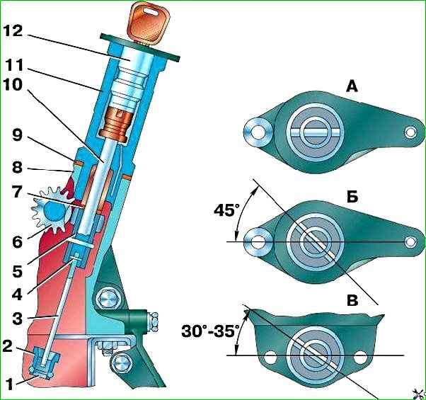
- 4. Rotate the drive shaft so that the slot on its end for the distributor awl is located as shown in Fig. 1 B, and use a screwdriver to turn the oil pump shaft to the position shown in Fig. 1 V.
- 5. Carefully, without touching the walls of the block with the gear, insert the drive into the block.
After installing the drive in place, its roller should take the position shown in Fig. 1 A.
To reduce wear on the drive joints, install the pump aligned with the drive bore.
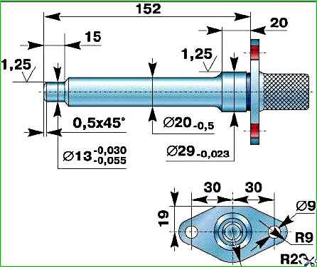
To do this, use a mandrel (Fig. 3), which fits tightly into the drive hole in the block and has a cylindrical shank with a diameter of 13 mm.
Center the pump along the shank of the mandrel and secure in this position.