The main defects of the cylinder head that can be eliminated by repair include: warping of the plane of contact with the cylinder block, wear of seats and valve guides
The non-straightness of the plane of the head in contact with the block, when checking it on the control plate with a feeler gauge, should not be more than 0.05 mm.
Minor warping of the head (up to 0.3 mm) should be eliminated by scraping the surface against the paint. For warpage exceeding 0.3 mm, the head must be ground.
Restoring valve tightness and replacing valve bushings
Violation of valve tightness with correct clearances between the valve stems and rocker arms, as well as with proper operation of the carburetor and ignition system, is detected by characteristic popping sounds from the muffler and carburetor.
The engine runs intermittently and does not develop full power.
Restore the tightness of the valves by grinding the working chamfers of the valves to their seats.
If there are cavities, ring grooves or scratches on the working chamfers of valves and seats that cannot be removed by lapping, grind the chamfers and then grind the valves to the seats.
Replace valves with warped heads.
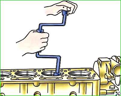
Rind the valve chamfers with a pneumatic or electric drill model 2213, 2447 GARO or manually using a brace.
Perform grinding using reciprocal rotational movements, in which the valve rotates in one direction slightly more than in the other.
For the period of grinding in, install a release spring with a slight elasticity under the valve.
The inner diameter of the spring should be about 10 mm.
The spring should slightly lift the valve above the seat, and when lightly pressed, the valve should sit on the seat.
The tool is connected to the valve using a rubber suction cup, as shown in Fig. 2.
For better adhesion of the suction cup to the valve, their surfaces must be dry and clean.
To speed up lapping, use a lapping paste made up of one part M20 micropowder and two parts engine oil.
Mixture thoroughly before use.
Begin grinding until a uniform matte chamfer appears on the working surfaces of the seat and valve plate along the entire circumference.
Towards the end of lapping, reduce the content of micropowder in the lapping paste.
Finish grinding in with one clean oil. Instead of lapping paste, you can use 00 emery powder mixed with engine oil.
For grinding the working chamfers of valves, it is recommended to use grinding machines of type R-108 or OPR-1841 GARO.
At the same time, clamp the valve rod in the centering cartridge of the headstock, installed at an angle of 44°30' to the working surface of the grinding stone.
Reducing the angle of inclination of the working chamfer of the valve head by 30' compared to the chamfer angle of the seats speeds up break-in and improves the tightness of the valves.
When grinding, remove a minimum amount of metal from the valve head chamfer.
The height of the cylindrical belt of the working chamfer of the valve head after grinding must be at least 0.7 mm, and the coaxiality of the working chamfer relative to the rod must be within 0.03 mm of the total indicator readings.
Valve stem runout is no more than 0.02 mm. Replace valves with large runout with new ones.
Do not re-grind the valve stems to a smaller size, as this will require making new valve spring retainers.
Grind the chamfers of the seats at an angle of 45° coaxially with the hole in the bushing. The chamfer width should be 1.6–2.4 mm.
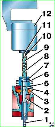
For grinding seats, it is recommended to use the device shown in Fig. 2.
Grind the seat without lapping paste or oil until the stone reaches the entire working surface.
After rough processing, change the stone to a fine-grained one and finish grinding the saddle.
The chamfer runout relative to the axis of the valve sleeve hole should not exceed 0.03 mm.
Replace worn seats with new ones.
Valve seats with an outer diameter larger than the nominal diameter by 0.25 mm are supplied as spare parts.
Remove worn seats from the head using a countersink.
After removing the sed Bored the sockets in the head for the exhaust valve to a diameter of 38.75+0.025 mm and for the intake valve to a diameter of 49.25+0.25 mm.
Before pressing the seats, heat the cylinder head to a temperature of 170°C, and cool the seats with dry ice.
Perform pressing quickly, without allowing the seats to heat up. The cooled head tightly covers the saddles.
To increase the strength of the seats, caulk them along the outer diameter using a flat mandrel, ensuring that the seat chamfer is filled.
Then grind to the required dimensions and lap.
If the wear of the valve stem and guide bushing is so great that the gap in their joint exceeds 0.25 mm, then restore the valve tightness only after replacing the valve and its bushing.
Spare parts are supplied with valves of only nominal sizes, and guide bushings with an internal diameter reduced by 0.3 mm for subsequent reaming to the final size after pressing into the cylinder head.
Extend the pressed bushings to a diameter of 9+0.022 mm.
The intake valve stem has a diameter of 9 –0.050 –0.075 mm, the exhaust valve has a diameter of 9 –0.075 –0.095 mm, therefore, the gaps between the intake and exhaust valve stems and bushings should be 0.050–0.097 mm and 0.075–0.117 mm, respectively.
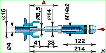
Press worn guide bushings out of the cylinder head using the drift shown in Fig. 3.
Press the new bushing from the rocker arm side using the same drift until it stops into the retaining ring on the bushing.
In this case, as when pressing valve seats, heat the cylinder head to a temperature of 170°C, and cool the sleeve with dry ice.
After replacing the valve bushings, grind the seats (centered on the holes in the bushings) and then grind the valves to them.
After grinding the seats and grinding the valves, rinse thoroughly and blow with compressed air all channels and places where abrasive could get in.
Valve bushings are metal-ceramic, porous.
After finishing and washing, saturate them with oil. To do this, insert a felt wick soaked in spindle oil into each bushing for several hours.
Before assembly, lubricate the valve stems with a thin layer of a mixture prepared from seven parts of an oil colloidal graphite preparation and three parts of engine oil.
Replacing valve springs
Possible malfunctions of valve springs that appear during operation may be: decreased elasticity, breaks or cracks in the coils.
Check the elasticity of the valve springs when disassembling the valve mechanism.
The force required to compress a new valve spring to 46 mm in height should be 267–310 N (27.3–31.7 kgf), and up to 37 mm – 686–784 N (70–80 kgf).
If the compression force of a spring up to 46 mm in height is less than 235 N (24 kgf), and up to 37 mm is less than 558.6 N (57 kgf), then replace such a spring with a new one.
Replace springs with breaks, cracks and traces of corrosion with new ones.
Replacing pushers
The guide holes in the block for the pushers wear out slightly, so restore the nominal clearance in this connection by replacing the worn pushers.
Only pushers of nominal size are supplied as spare parts.
Select pushers to holes with a gap of 0.040–0.015 mm.
Pushers, depending on the size of the outer diameter, are divided into two groups and are marked with a stamp: number 1 - for a pusher diameter of 25 -0.008 -0.015 mm and number 2 - for a pusher diameter of 25 -0.015 -0.022 mm.
A correctly selected pusher, lubricated with liquid mineral oil, should smoothly lower under its own weight into the block socket and rotate easily in it.
Pushers that have radial scuffing at the ends of the plates, wear or chipping of the working surface, replace them with new ones.
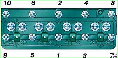
Tighten the cylinder head nuts after running in the vehicle, after 1000 km and after each head removal.
Tighten the nuts only on a cold engine in the sequence shown in Fig. 4 in two steps.
Final tightening torque 71.5–76.5 Nm (7.3–7.8 kgf m).
As necessary, clean the cylinder head, piston crowns and intake valves from carbon deposits.
On a serviceable, unworn engine, using high-quality fuel and oil and observing When the proper thermal conditions are maintained, deposits are small.
When the engine wears out, especially its piston rings, a lot of oil gets into the combustion chambers and a large layer of carbon deposits forms.
The presence of carbon deposits is determined by increased detonation, overheating, loss of power and increased fuel consumption.
If these signs appear, remove the cylinder head and remove carbon deposits using metal scrapers and brushes.
Do not allow carbon deposits to get into the gap between the piston heads and cylinders.
If the engine was running on leaded gasoline, first moisten the carbon deposits with kerosene to prevent the possibility of inhaling toxic dust during cleaning.