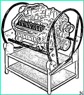
To assemble the engine, as well as to disassemble it, the engine cylinder block assembled with the clutch housing is fixed on a stand (see Fig. 1)
Before assembly, all engine parts are selected according to size, thoroughly washed, blown with compressed air and wiped with clean napkins
All threaded connections (studs, plugs, fittings, etc.), if they were removed during disassembly or were replaced, must be installed with red lead or white lead diluted with natural drying oil.
Permanent connections (block plugs and cylinder heads) are installed using nitro varnish.
The following are not allowed to be installed on the engine being repaired:
- - used cotter pins and cotter wire;
- - spring washers that have lost their elasticity;
- - bolts and studs with extended threads;
- - nuts and bolts with worn edges;
- - parts that have more than two nicks or dents on the thread or broken threads;
- - damaged gaskets.
Assemble the engine in the reverse order of disassembly.
The preparation of parts for engine assembly can be found in the article - Preparation of components and parts for assembling the ZMZ-53 engine
The following are specific recommendations and additional requirements for engine assembly.
When replacing cylinder liners, before installation, the liner is selected according to the socket in the cylinder block.
Sleeves are selected using an accurate metal ruler and a set of feeler gauges as follows:
- the liner, installed in its place in the cylinder block without sealing gaskets, must be recessed relative to the mating surface of the cylinder block.

The ruler is placed on the mating surface, and the probe is inserted into the gap between the ruler and the end of the liner (Fig. 2).
The thickness of the gasket is chosen in such a way that after installing the liner with the gasket, its elevation above the surface of the cylinder block is ensured within 0.02-0.09 mm.
Sealing gaskets are available in different thicknesses:
- 0.3; 0.2; 0.15 and 0.1 mm. Depending on the gap, one or another gasket is put on the cylinder liner; sometimes the required value is obtained by a set of gaskets of various thicknesses.
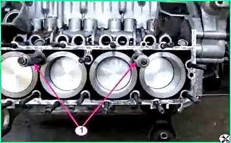
After installation into the cylinder block, the liners are secured with clamping bushings (see Fig. 3).
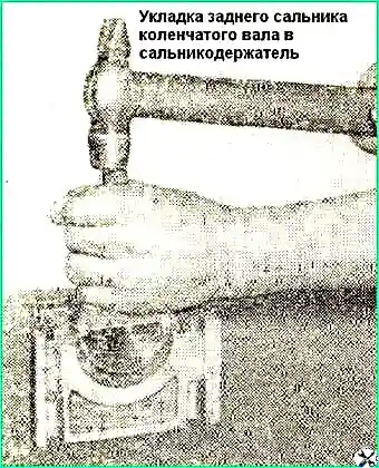
Asbestos cord impregnated with an oil-graphite mixture is used as a rear oil seal on engines.
A cord 140 mm long is placed in the sockets of the cylinder block and oil seal holder.
Using the device, the cord is pressed into its sockets with light blows of a hammer, as shown in Fig. 4.
Without removing the device, cut the ends of the cord flush with the plane of the gland holder connector.
The cut must be smooth; fraying of the ends and uneven cuts are not allowed.
When assembling the crankshaft with the flywheel and clutch, observe the following requirements.
The flywheel mounting nuts are tightened, providing a torque of 7.6-8.3 kgm.
When assembling the clutch, the driven disk is installed with a damper to the pressure disk and centered on the crankshaft bearing (the drive shaft of the gearbox can be used as a mandrel).
The “O” marks stamped on the pressure plate and flywheel housing near one of the holes for the housing mounting bolts must be aligned.
The crankshaft, flywheel and clutch assembly must be dynamically balanced. Permissible imbalance 70 Gsm.
When balancing, remove excess mass from the heavy side by drilling out the flywheel metal at a distance of 6 mm from the ring gear with a drill with a diameter of 8 mm to a depth of no more than 10 mm.
If there is an imbalance the assembled shaft exceeds 180 Gcm, the shaft is disassembled and each part is balanced separately.
The flywheel imbalance should not exceed 35 Gcm;
imbalance of the pressure plate assembly with the casing - 36 Gcm;
Unbalance of the driven disk—18 Gcm.
On assembling the crankshaft, see the article - Assembling the crankshaft with flywheel and clutch and installing it in the cylinder block
Main bearing caps are installed so that the locking lugs of the liners are on one side, and the numbers or marks stamped on the caps correspond to the bed numbers.
When installing the front cover, it is necessary to ensure that the fixing tendril of the rear thrust bearing washer fits into the groove of the cover, and that no steps are formed between the end of the cover and the end of the cylinder block.
Tighten the nuts securing the main bearing caps (torque 11-12 kgm).
After tightening and cottering the main bearing cap nuts, the crankshaft should rotate easily with little effort.
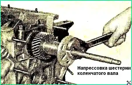
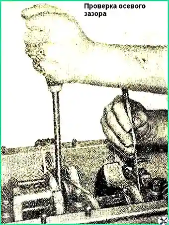
After pressing the crankshaft gear (Fig. 5), using a puller and a thrust bushing, check the axial clearance of the crankshaft, to do this, press the crankshaft to the rear end of the engine and, using a feeler gauge, determine the gap between the end of the rear thrust bearing washer and the end of the front main crankshaft journals (Fig. 6).
The gap should be within 0.075 - 0.175 mm.
When assembling parts of the connecting rod and piston group, the following requirements must be observed.
Piston pins are selected to the connecting rods so that at room temperature (+18° C) the lightly lubricated pin moves smoothly in the connecting rod bore under light pressure from the thumb.
Before assembly, the pistons are heated in hot water to +70° C.
Pressing a pin into a cold piston is not allowed, as this can lead to damage to the surfaces of the piston boss holes, as well as to deformation of the piston itself.
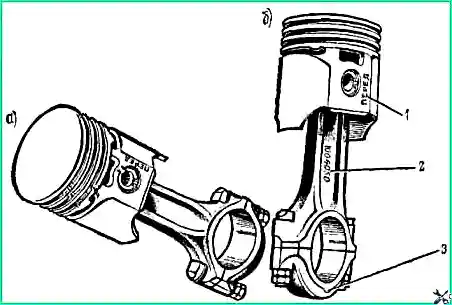
Connecting rods and pistons during assembly are oriented as follows: for pistons of the first, second, third and fourth cylinders, the inscription on the piston “in front” and the number stamped on the connecting rod rod must be directed in opposite directions, and for the pistons of the fifth, sixth, seventh and eighth cylinders - in one direction (Fig. 7).
The piston pin retaining rings are installed in the grooves of the piston bosses so that the bend of the tendril is directed outward.
Piston rings are selected according to the liners in which they will work.
The gap measured at the joint of the ring placed in the sleeve should be in the range of 0.3-0.5 mm for compression and oil scraper rings.
A chrome-plated compression ring is installed in the upper piston groove, and a tin-plated compression ring is installed in the second groove with a recess on the inside towards the bottom.
Before installation in the cylinder liners, the joints of the piston rings should be positioned at an angle of 120° to each other, and protective brass caps should be put on the connecting rod bolts to avoid accidental damage to the surface of the connecting rod journals.
When installing pistons into cylinder liners, make sure that the inscription “front” on the piston is directed towards the front end of the cylinder block.
Tighten the connecting rod bolt nuts (torque 6.8 - 7.5 kgm) and lock.
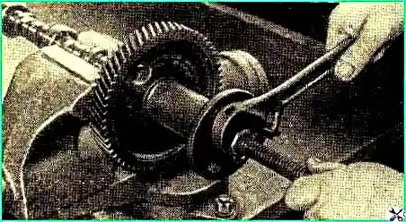
After pressing the gear onto the camshaft (Fig. 8), use a feeler gauge to check the axial clearance between the thrust flange and the end of the camshaft gear. The gap should be within 0.08 - 0.2 mm.
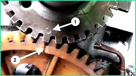
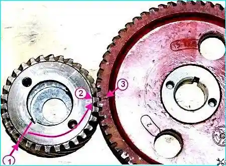
When engaging the timing gears, the crankshaft gear tooth marked “O” must enter the cavity of the camshaft gear teeth marked with a mark.
Replace the gears as a set, since they are selected at the factory based on lateral clearance and noise during operation.
The lateral clearance in the engagement should be in the range of 0.03-0.08 mm.
In order not to make a mistake when assembling and installing the gears, you need to take into account that the mark on the crankshaft gear is located on the 12th tooth, counting from the tooth opposite the slot for the key counterclockwise (Figure 11).
When installing on the cylinder block, center the timing gear cover on the front end of the crankshaft using a tapered mandrel to prevent the crankshaft front oil seal from running on one side.
Place a tapered reference on the front end of the crankshaft and press the timing gear cover against the cylinder block using a ratchet, then tighten the cover securing nuts.
The sealing gasket of the oil pickup tube should be placed in the socket in the cylinder block, and not put on the tube.
Before installation on the engine, the oil pump is filled with oil.
When assembling the cylinder heads, the new valve stems are coated with a mixture consisting of seven parts of a colloidal graphite preparation and three parts of aviation oil.
The rocker arm axles are assembled in such a way that the holes for the mounting studs in the axle and racks are shifted in the opposite direction from the rocker arm adjusting bolts.
The intake manifold mounting nuts are tightened with moderate force, since the rubber gaskets cannot limit the tightening to the stop and when the nuts are tightened, the rubber gaskets may be crushed.
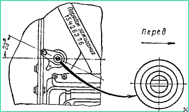
The breaker-distributor drive must be installed in this sequence.
Set the piston of the 1st cylinder to the top dead center (TDC) position on the compression stroke.
Insert the breaker-distributor drive into the hole in the cylinder block so that the slot in the drive shaft is directed along the engine axis and shifted to the left, counting as the vehicle moves.
Secure the drive housing with a holder and a nut so that the bracket with a threaded hole for fastening the breaker-distributor is directed back and turned at an angle of 23˚ to the left from the longitudinal axis of the engine, as shown in Fig. 10.
Before installing the distributor-breaker on the engine, you should check the gap in the breaker contacts and, if necessary, adjust it.
The gap in the contacts should be within 0.3-0.4 mm.
Use the octane corrector nuts to turn the body of the breaker-distributor so that the arrow points to the zero scale division.
Turn the distributor rotor so that it faces the terminal of the first cylinder.
The terminal of the first cylinder on the ignition distributor cap is marked with the number “1”.
Place the distributor cap with the wires and connect the latter to the spark plugs in the order of operation of the engine cylinders (1-5-4-2-6-3-7-8). The ignition order is cast on the engine intake manifold.
")

")
")
")
")
")
")
")